Rockwell Automation Publication 20Y-TG001C-EN-P - April 2017 53
AFE Power Structure Component Section Chapter 4
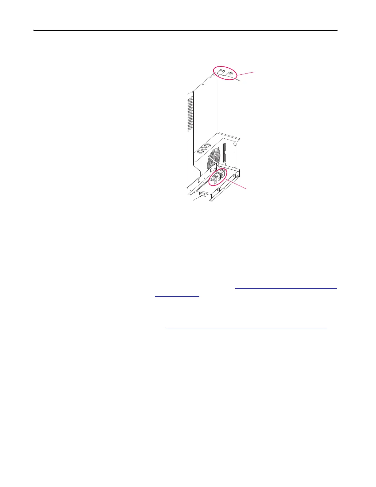
5. Remove the connections from the DC bus terminals at the top of the
power structure.
6. Remove the U/T1, V/T2, and W/T3 connections from the power
structure at the bottom front of the power structure.
7. Remove the ground connection from the rear of the power structure.
8. Disconnect the seven fiber-optic cables that are connected to the fiber-
optic adapter board located behind the control assembly (for AFE in
IP20 2500 MCC Style enclosure) or the control frame (for AFE in IP21
Rittal enclosure).
For location of connections, see Remove the Fiber-optic Adapter Circuit
Board on page 40.
9. To access the X3 fan connector, remove the protective front cover and
terminal cover from the power structure.
See Remove Protective Covers from the Power Structure
on page 46.
10. Remove the X3 fan connector.
Ground
Connection
DC Bus Terminals
U/T1, V/T2, and
W/T3 Connections
 Loading...


