EasyManuals Logo
Home>Allen-Bradley>Controller>PowerFlex AFE

Allen-Bradley PowerFlex AFE User Manual

Allen-Bradley PowerFlex AFE
134 pages
To Next Page IconTo Next Page
To Previous Page IconTo Previous Page
Page #54 background imageLoading...
Page #54 background image
54 Rockwell Automation Publication 20Y-TG001C-EN-P - April 2017
Chapter 4 AFE Power Structure Component Section
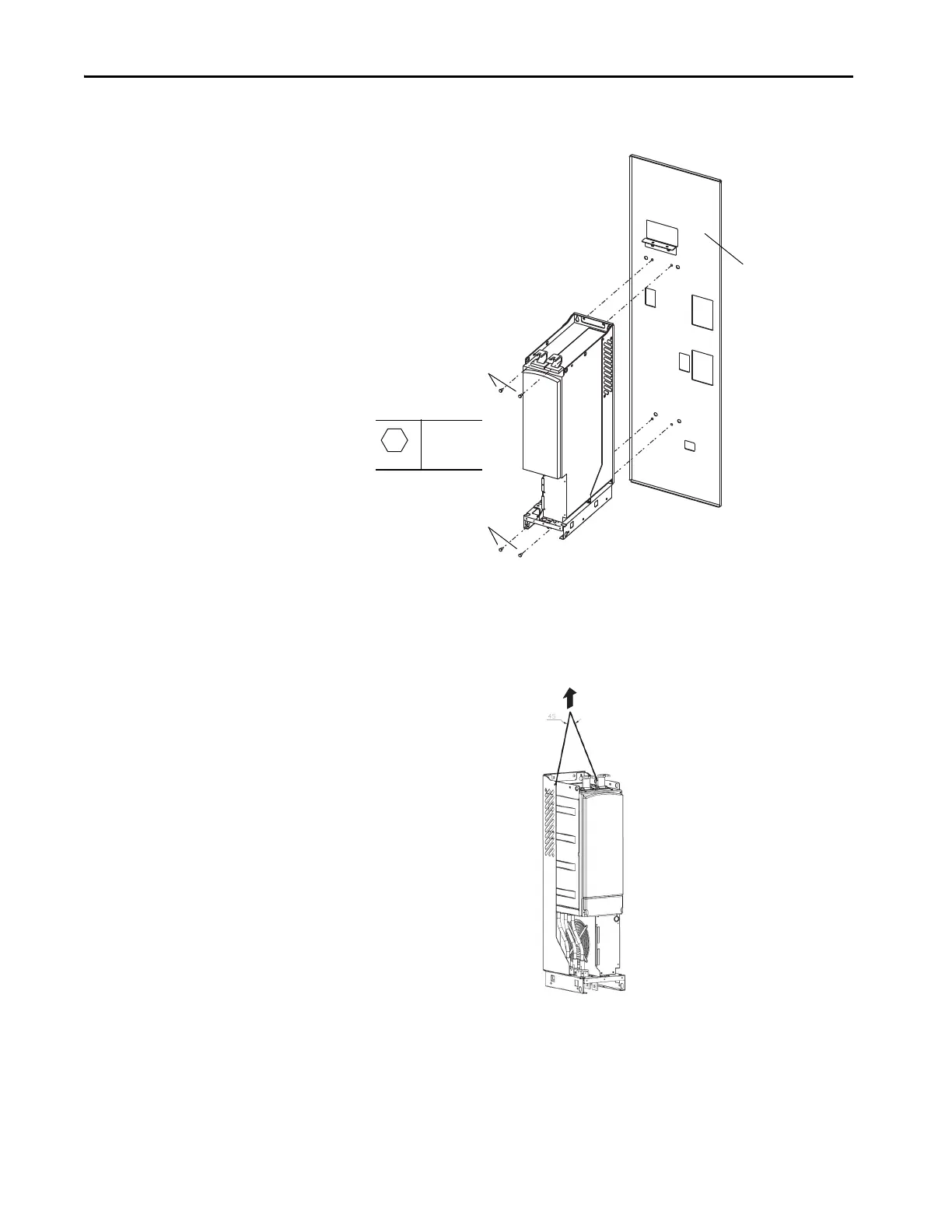
11. Remove the four M8 x 20 screws that secure the power structure to the
enclosure back panel.
12. To expose the lifting holes, partially pull the power structure forward
from the enclosure.
13. Secure an appropriate lifting apparatus to the power structure and
remove the power structure (approximately 99.8 kg [220 lb]) from the
enclosure.
Remove Screws
M8 x 20
6.7 N•m
(60 lb•in)
Remove Screws
For clarity, only the back
panel of the enclosure is
shown.

Table of Contents

Questions and Answers:

Question and Answer IconNeed help?

Do you have a question about the Allen-Bradley PowerFlex AFE and is the answer not in the manual?

Allen-Bradley PowerFlex AFE Specifications

General IconGeneral
BrandAllen-Bradley
ModelPowerFlex AFE
CategoryController
LanguageEnglish

Related product manuals