Version 1.6 ©Copyright 2020, Ambient LLC. All Rights Reserved. Page 7
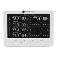
Graph for Temperature/Dew point/heat
index/humidity of Indoor/outdoor
sensors.
Outdoor Temperature/Dew point/heat
index/humidity for channel 4 and other
channels defined to be displayed in
CH4 area.
Outdoor Temperature/Dew point/heat
index/humidity for channel 5 and other
channels defined to be displayed in
CH5 area.
Outdoor Temperature/Dew point/heat
index/humidity for channel 1 and other
channels defined to be displayed in CH1
area.
Outdoor Temperature/Dew point/heat
index/humidity for channel 2 and other
channels defined to be displayed in CH2
area.
Radio Controlled Clock reception icon.
Outdoor Temperature/Dew point/heat
index/humidity for channel 3 and other
channels defined to be displayed in CH3
area.
2.4.2 Sensor Operation Verification
Verify the humidity sensors match closely with all of the sensors in the same location (about 5 to 10’
apart). The sensors should agree within 10% (the accuracy is ± 5%). Allow about 30 minutes for all
sensors to stabilize. The humidity can be adjusted or calibrated later to match each other a known
source.
Verify the temperature sensors match closely with all of the sensors in the same location (about 5 to
10’ apart). The sensors should be within 4°F (the accuracy is ± 2°F). Allow about 30 minutes for all
sensors to stabilize. The temperature can be adjusted or calibrated later to match each other or a
known source.
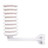
3 Remote Sensor Installation
If you mount one or more of the sensors outside, it is recommended you mount the sensor in a shaded
area. Direct sunlight and radiant heat sources will result in inaccurate temperature readings. Although
the sensors are water resistant, it is best to mount in a well-protected area, such as under an eve. Use a
screw to affix the remote sensor to the wall, as shown in Figure 6.
Alternately, you can hang the sensor with fishing wire or a string. This insures the sensor does not
come into contact with any radiant heat source.

 Loading...