8 Pre-Installation Settings AXB-F117 Stealth 1 Camera Controller
RS-232 DIP switch (S1) settings
Position 1 2 3 4 5 6 7 8
Function Stop Bits Data Bits Parity Baud Rate
Off Off Off Off Off Off Off Off
2 bits 7 bits Unused 300
On On On Off Off On Off Off
1 bit 8 bits Unused 600
Off On Off Off On Off
Unused 1,200
On On Off On On Off
Unused 2,400
Off Off On Off Off On
Unused 4,800
On Off On On Off On
Even 9,600
Off On On Off On On
Odd 19,200
On On On On On On
None 38,400
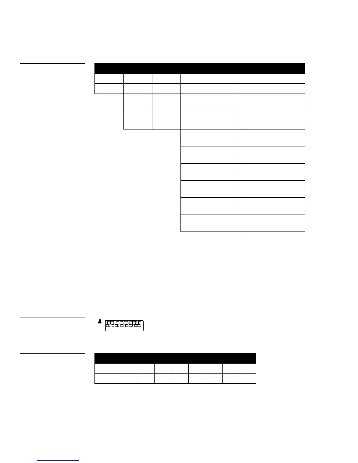
Setting the AXlink Device DIP switch (S2)
The 8-position Device DIP switch (S2), shown in Figure 9, sets the AXlink device
number. The device number must match the number assigned in the AXCESS
software program. The AXlink device number range is 1-255, and is sent according
to the Device DIP switch positions and their values (Figure 10). The Device DIP
switch example shown in Figure 9 is set to 90 (2 + 8 + 16 + 64 = 90), which is the
factory default setting.
Device DIP switch (S2) settings
Position
1 2 3 4 5 6 7 8
Value
1 2 4 8 16 32 64 128
Figure 8
RS-232 DIP switch (S1)
Note
After setting the AXlink device
number, remove and
reconnect the AXlink
connector on the AXB-F117
to store the new number into
Figure 9
AXlink Device DIP switch
Figure 10
Device DIP switch (S2)
 Loading...