AXB-F117 Stealth 1 Camera Controller Installation 17
Wiring the Connectors
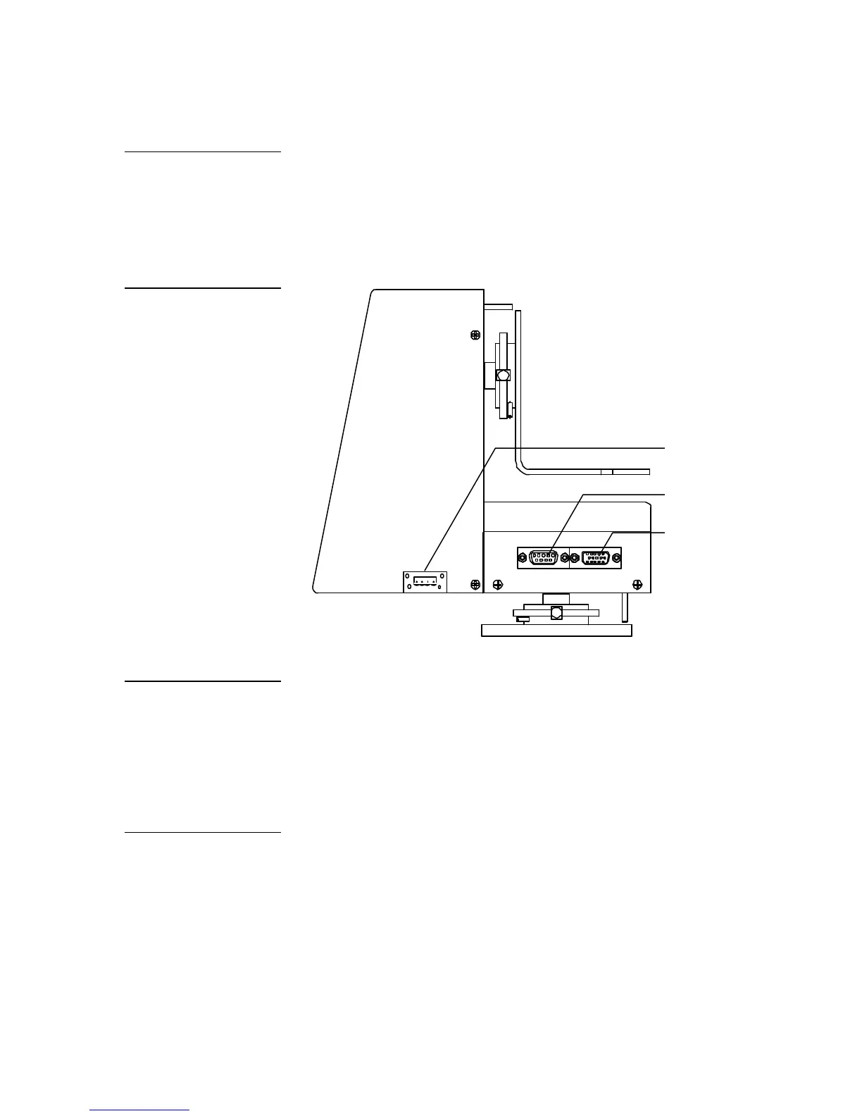
The AXB-F117 has an AXlink 4-pin connector, a camera control RS-232 DB-9
connector, and lens control DB-15 high-density connector. Figure 20 shows the
location of each connector on the AXB-F117.
AXlink 4-pin (male)
Camera control RS-232
Lens control DB-15 high-
density (female) connector
Preparing captive wires
You will need a wire stripper, soldering iron, and flat-blade screwdriver to prepare
and connect the captive wires.
1. Strip 0.25 inch of insulation off all wires and apply a light coat of solder to the
ends using a soldering iron.
2. Insert each wire into the appropriate opening on the connector according to
the wiring diagrams and connector types described in this section.
3. Turn the flat-head screws clockwise to secure the wire in the connector.
Caution
Before applying power to the
AXB-F117, set the adjustable
pan/tilt-limit stops to a safe
position to prevent camera or
Figure 20
AXlink connector, camera
control RS-232 DB-9
connector, and lens control
DB-15 high-density (female)
Caution
Do not connect power to the
AXB-F117 until the wiring is
complete. If you are using a
12 VDC power supply, apply
power to the AXB-F117 only
after installation is complete.
Caution
Do not over-torque the
screws; doing so can bend
the seating pin and damage
 Loading...