AXB-F117 Stealth 1 Camera Controller Pre-Installation Settings 9
Setting Internal Jumpers to AXlink or RS-232 Communication
Mode
Jumpers E5 through E7, located on the circuit card inside the AXB-F117, set the
communication mode to AXlink (factory default) or RS-232. You need a Phillips-
head screwdriver to open the unit and non-conducting pliers to set the jumpers.
1. Discharge the static electricity from your body.
2. Unplug all connectors from the rear panel of the AXB-F117.
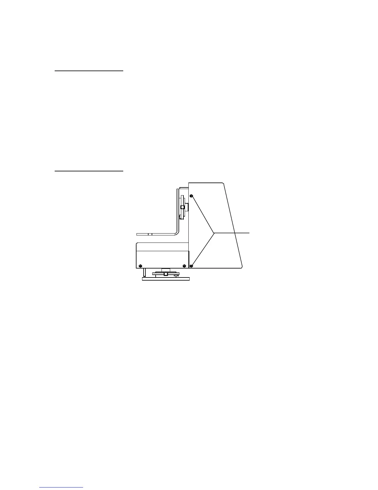
3. Remove the four pan-head screws from the left and right side of the AXB-F117
unit as shown in Figure 11.
Pan-head screws (two
4. Carefully pull the back panel away from the main unit far enough to lay the
back panel down on a flat surface, and locate the E5, E6, and E7
communication mode jumpers (Figure 12).
Note
Static electricity can damage
electronic circuitry. Before
removing the enclosure,
discharge any accumulated
static electricity from your
body by touching a grounded
Figure 11
Pan-head screws locations
 Loading...