AG2014 70 CM REFRIGERATORS 13.11.2013 / REV NO:
00
42
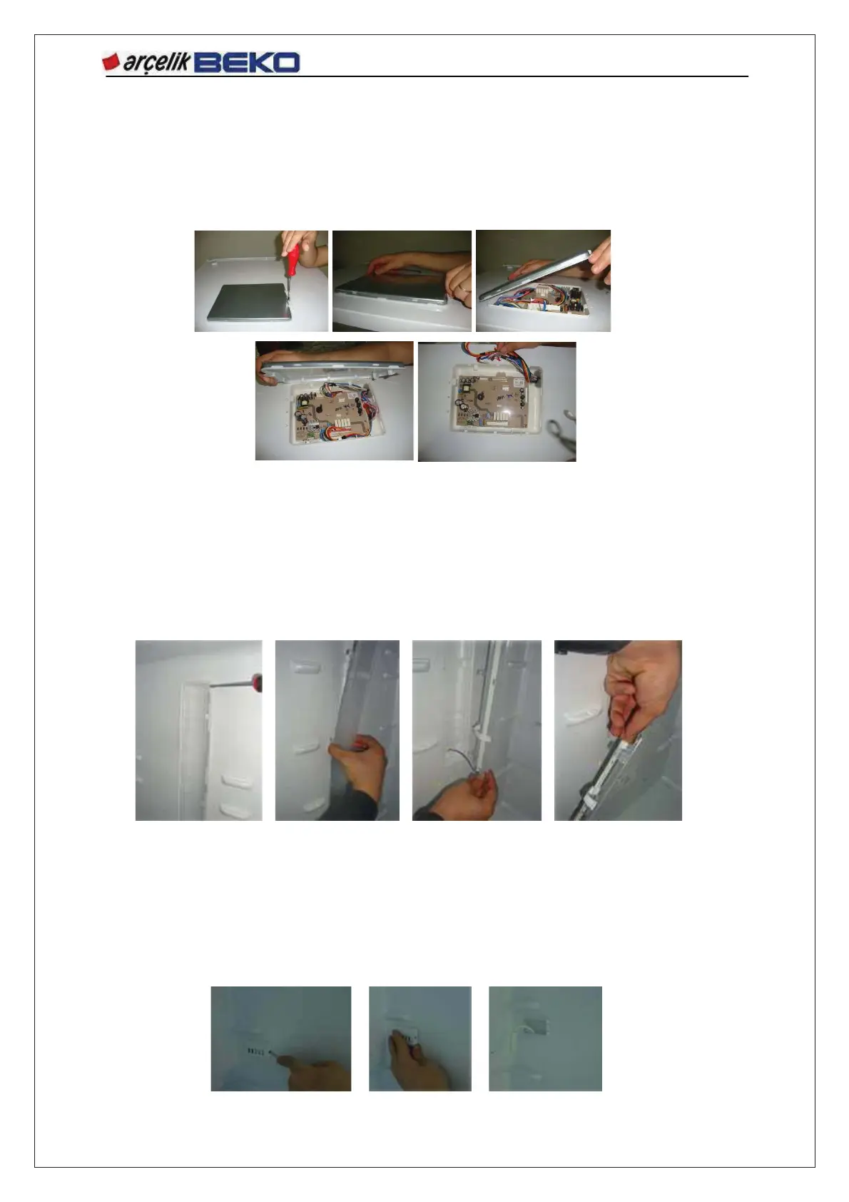
14.5. Board Cover and Electronic Boards
Board slot is located on the upper sheet iron of the refrigerator. Single fitting screw has to be
unscrewed to remove the board cover assembly and the board box cover must be removed. Main
board is locked by means of tabs. Boards can be detached by releasing from these tabs and removing
socket connections.
14.6. Fridge Compartment Illumination Group and LED Board
The illuminating glass shown in the picture is fixed on the interior body plastic by snapped tabs.
Screw-less connection is used. To remove the illumination glass, it is slightly pulled apart from upper
or lower corners by means of a pointed tool in the order shown in the picture and then it is pulled out
manually to release from the interior body. Once the illumination glass is removed, the LED board
inside can be accessed. To remove the LED board, connection with socket shall be detached and the
LED board shall be removed.
To attach this group, same processes should be applied in reverse order.
NOTE: ESD measures must be taken throughout these processes!
14.7. Sensor Cover
Sensor cover is secured with a tab connection. To remove it, the tab seen at the side shall be pressed
and the cover shall be pulled out to remove.
 Loading...