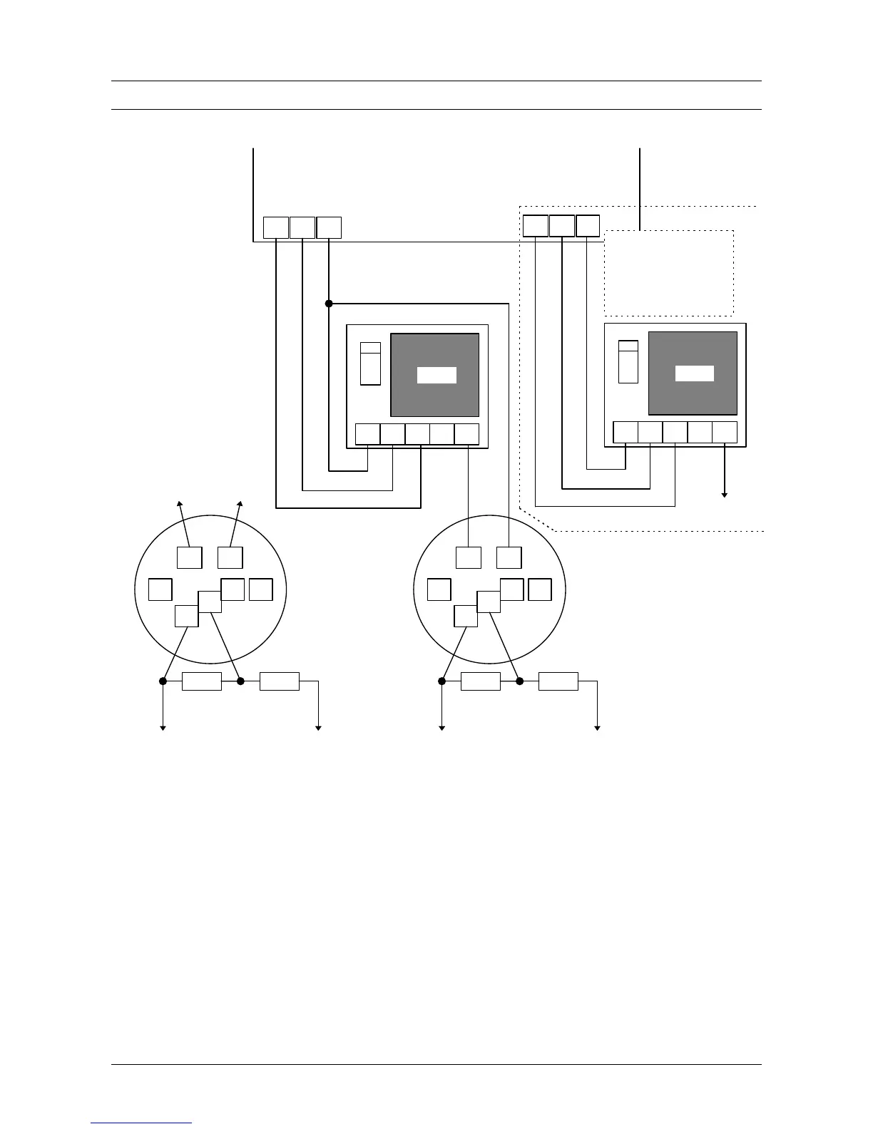
EasyManuals Logo
Home>Aritech>Control Panel>ADVISOR CD95

Aritech ADVISOR CD95 Installation Manual

Aritech ADVISOR CD95
40 pages
To Next Page IconTo Next Page
To Previous Page IconTo Previous Page
Page #25 background imageLoading...
Page #25 background image
Installation manual for the CD72/95/15012 Page 25
CONNECTING A FIRE DETECTOR
+
O1
-
1
5
2
1
6
NC
CD72/95/150
DB822
+
DP803
NO
C
4K7
4K7
To “fire” zone
2
3
4
5
RC213
4
1
2
3
7
DB602
+
DP611/
DI612/
DT613
9
8
4K7
4K7
To “fire” zone
1
2
3
4
5
RC213
+
O3
O2
To siren
control (Sc)
This extra connection is
only necessary if a
continuous signal from
the external siren is
required
To terminal “5
of the RC213
relay.
OR
To “+
terminal of
the panel
O1 = “Fire reset -
O2 = “External siren
O3 = “Fire -
Figure 20. Connecting a fire detector
Note 1: If there are several detectors place them in parallel and cable the zones as described in
figure 1 or 2 (see page 8).
Note 2: This connection also applied for detectors which require a reset after an alarm, e.g. the
GS900 etc.
Note 3: The reset is performed after the second entry of a code after an alarm.
Note 4: Programme zone loop as “Dual”.
Note 5: Programme all outputs for negative applied “-”.

Other manuals for Aritech ADVISOR CD95

Questions and Answers:

Question and Answer IconNeed help?

Do you have a question about the Aritech ADVISOR CD95 and is the answer not in the manual?

Aritech ADVISOR CD95 Specifications

General IconGeneral
BrandAritech
ModelADVISOR CD95
CategoryControl Panel
LanguageEnglish

Related product manuals