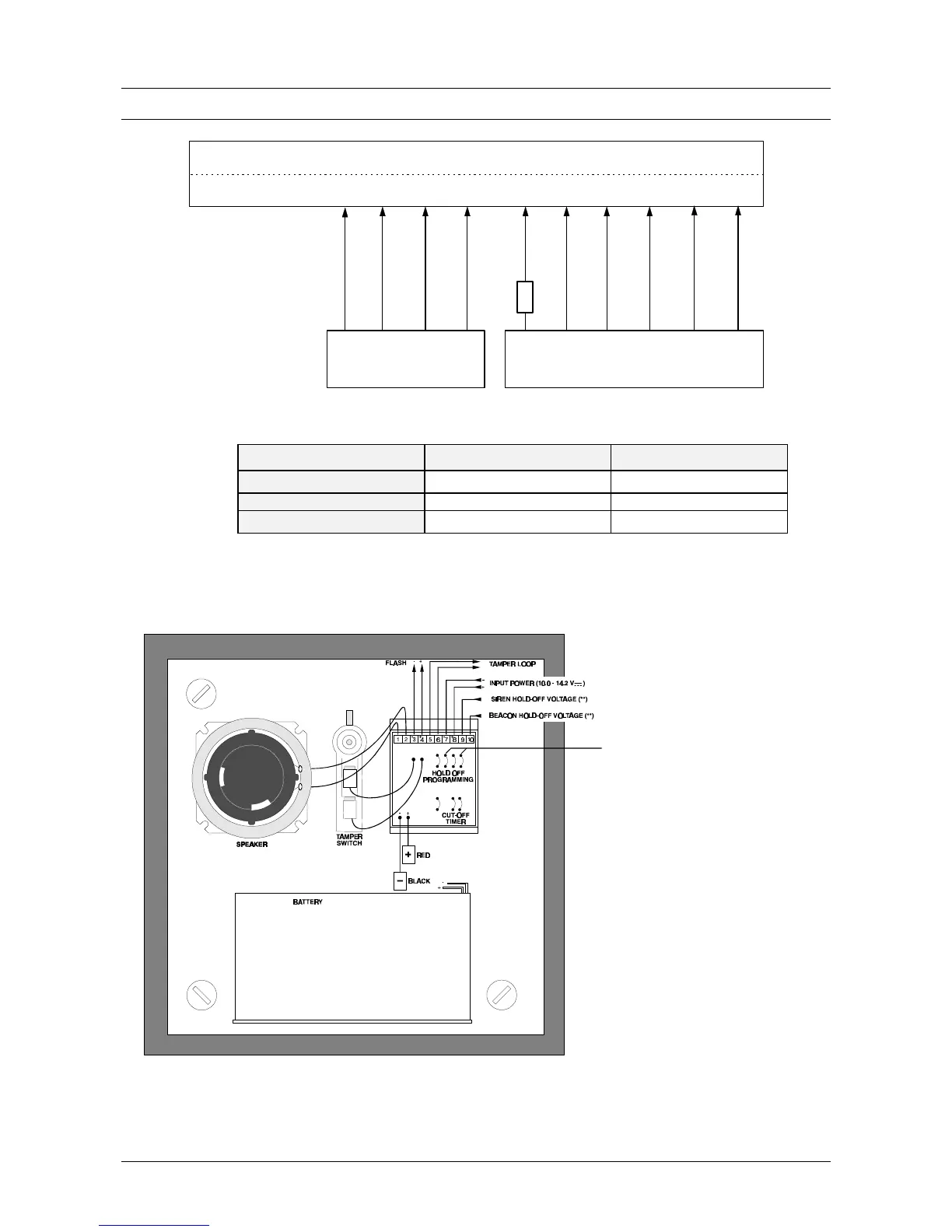
Figure 22. Connecting the AS294/394 + internal siren AS256
Programming CD72 CD95/150
Beacon control 01 Int Sir Sy + 01 Int Sir Sy +
Internal siren control 18 Int Sir Sy - 49 Int Sir Sy -
External siren control 19 Ext Sir Sy + 50 Ext Sir Sy +
Table 4. Programming for the sirens
NB: If the tampers must be placed in separate zones, they can be connected according to figure 1 (1 end-
loop resistor) or figure 2 (2 end-loop resistors) (see page 8).
Figure 23. Connecting the AS294/394
Cut these 2 jumpers for
negative Hold-Off.
The other 2 jumpers for
positive Hold-Off.
 Loading...