Page 8 Installation manual for CD72/95/15012
BEFORE SWITCHING ON THE POWER
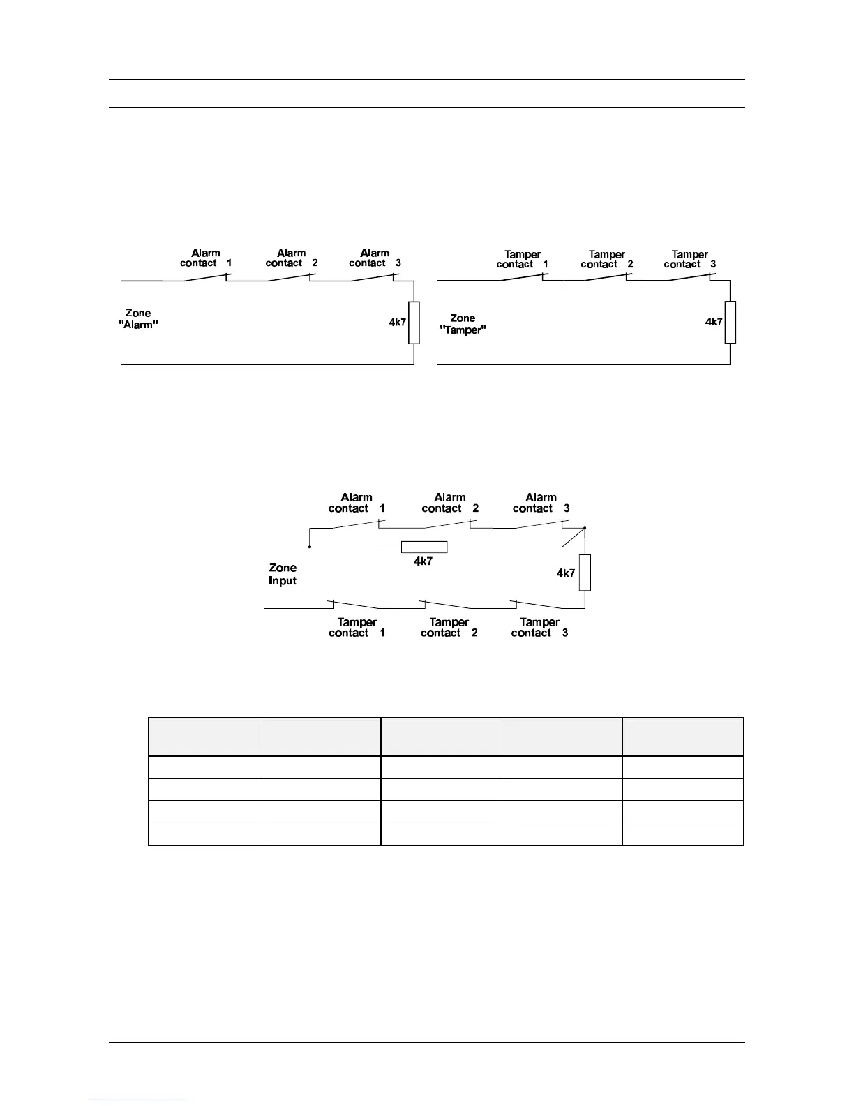
1. Detectors (or key switches) can be connected in two ways:
Conventional: One zone each is required for both tamper and the alarm. Both zones should be
closed with an end-loop resistor (4.7 kOhm). Program the ‘zones’ menu as ‘Alarm’
Figure 1. Separate alarm and tamper connection
Dual loop: The alarm and tamper are placed together in one zone. The zone has two end-loop
resistors (4.7 kOhm) to differentiate between alarm and tamper. Figure 2 shows how
they are connected. Program the ‘zones’ menu as ‘Dual’.
Figure 2. Joint Connecting the alarm & tamper
This connection method gives the following input values:
The zone is Resistance Panel zone
voltages
Remote zone
voltages
Reaction
on standby 3k5 - 6k2 2.1 - 2.8 V 4.7 - 6.8 V none
triggered 6k6 - 11k7 2.9 - 3.6 V 6.9 - 8.6 V alarm
open > 12k7 > 3.7 V > 8.7 V tamper
short-circuited < 2k9 < 1.9 V < 4.6 V tamper
Table 1. Operation of the inputs
 Loading...