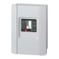
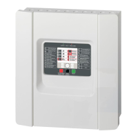
Page 26 Installation manual for the CD72/95/15012
OUTPUTS
Panel Internal siren External siren Output expander
CD72 1....5 18 19
CD95/150 1....8 49 50 41....48
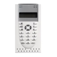
Keypad 1 Remote 2 Remote 3 Remote 4 Remote 5 Remote 6 Remote 7 Remote 8
OA OB OA OB OA OB OA OB OA OB OA OB OA OB OA OB
CD72 6 7 8 9 10 11 12 13 14 15 16 17
CD95/150 9 10 11 12 13 14 15 16 17 18 19 20 21 22 23 24
Remote 9 Remote10 Remote11 Remote12 Remote13 Remote14 Remote15 Remote16
OA OB OA OB OA OB OA OB OA OB OA OB OA OB OA OB
CD150 25 26 27 28 29 30 31 32 33 34 35 36 37 38 39 40
Table 3. Numbering of the outputs
NB: In a keypad OA is the buzzer. OB does not exist in a CD3008 / CD3009 keypad.
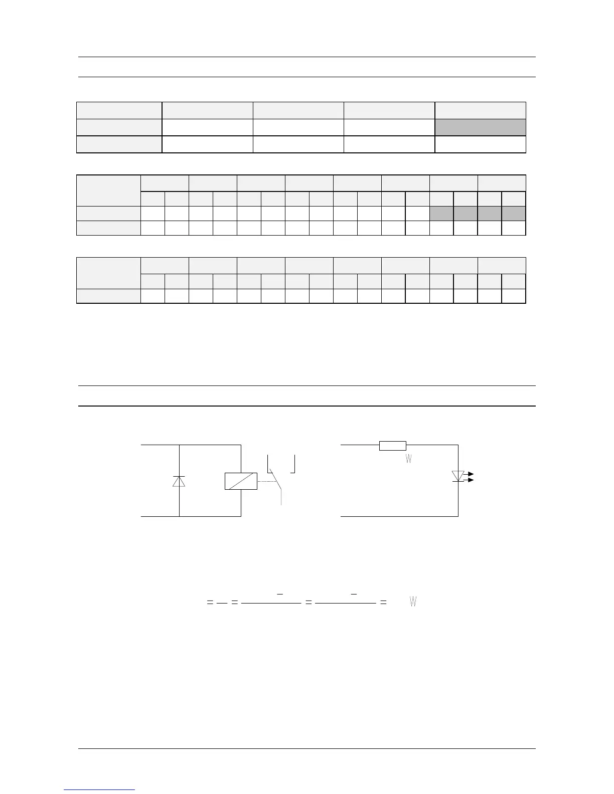
CONNECTING A RELAY OR AN LED
Output
+12 Volt
NC NO
C
+12 Volt
R = 820
Output
Figure 21. Connecting a relay or an LED on the output
The resistor R is necessary to adjust the current. This may not be greater than 40 mA. For most LEDs,
however, a current of approximately 15 mA is sufficient. The resistance calculation is as follows:
R
 Loading...