Installation manual for CD72/95/15012 Page 5
CONTENTS
INSTALLATION GUIDELINES ..................................................................................................... 7
Before switching on the power..................................................................................................... 8
Figure 1. Separate alarm and tamper connection ............................................................... 8
Figure 2. Joint Connecting the alarm & tamper................................................................... 8
Figure 3. Overview of the dipswitches on remotes.............................................................. 9
PROGRAMMING GUIDE.......................................................................................................... 11
Figure 4. Keys on a CD30xx.............................................................................................. 11
Returning to default settings...................................................................................................... 12
Leaving programming mode...................................................................................................... 13
Dialler........................................................................................................................................ 13
Other manuals........................................................................................................................... 13
INSTALLATION GUIDE ........................................................................................................... 14
Wiring diagrams CD72 .............................................................................................................. 14
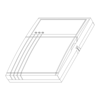
Figure 5. CD72 cabinet...................................................................................................... 14
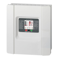
Figure 6. CD72 control panel............................................................................................. 15
Wiring diagrams CD95/150 ....................................................................................................... 16
Figure 7. CD95 cabinet...................................................................................................... 16
Figure 8. CD150 cabinet.................................................................................................... 16
Figure 9. CD95/150 control panel...................................................................................... 17
Opening CD3008 / CD3048 keypad .......................................................................................... 18
Figure 10. Opening the CD3008 / CD3048 keypad.......................................................... 18
Opening CD3009 / CD3049 keypad .......................................................................................... 18
Figure 11. Opening the CD3009 / CD3049 keypad........................................................... 18
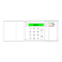
CD3008 / CD3009 keypad......................................................................................................... 19
Figure 12. CD3008 / CD3009 keypad ............................................................................... 19
CD3048 / CD3049 keypad......................................................................................................... 19
Figure 13. CD3048 / CD3049 keypad ............................................................................... 19
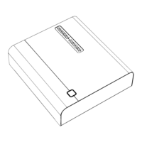
CD9031 expander ..................................................................................................................... 20
Figure 14. CD9031 expander ............................................................................................ 20
Keypad back tamper ................................................................................................................. 21
Connecting an extra power supply............................................................................................. 22
Figure 15. Use of an extra power supply........................................................................... 22
Inputs ........................................................................................................................................ 22
Connecting a detector without memory ..................................................................................... 23
Figure 16. Dual loop Connecting a detector without memory............................................ 23
Connecting a detector with Latch .............................................................................................. 23
Figure 17. Dual loop Connecting a detector with latch......................................................23
Connecting a key switch............................................................................................................ 24
Figure 18. Connecting a key switch with LED's................................................................. 24
Connecting a “nitewatch” system............................................................................................... 24
Figure 19. Connecting a CP4005 Nitewatch PCB.............................................................24
 Loading...