EasyManuals Logo

Asus M4N68T-M LE User Manual

Asus M4N68T-M LE
62 pages
To Next Page IconTo Next Page
To Previous Page IconTo Previous Page
Page #35 background imageLoading...
Page #35 background image
6. System panel connector (10-1 pin F_PANEL)
This connector supports several chassis-mounted functions.
M4N68T-M LE
M4N68T-M LE System panel connector
PIN 1
PWR BTN
PLED+
PLED-
PWR
GND
IDE_LED+
IDE_LED-
Ground
Reset
F_PANEL
PWR LED
HD_LED RESET
System power LED (2-pin PWRLED)
This 2-pin connector is for the system power LED. Connect the chassis power LED
cable to this connector. The system power LED lights up when you turn on the system
power, and blinks when the system is in sleep mode.
Hard disk drive activity LED (2-pin HDLED)
This 2-pin connector is for the HDD Activity LED. Connect the HDD Activity LED cable
to this connector. The HDD Activity LED lights up or ashes when data is read from or
written to the HDD.
Power/Soft-off button (2-pin PWRBTN)
This 2-pin connector is for the system power button.
Reset button (2-pin RESET)
This 2-pin connector is for the chassis-mounted reset button for system reboot without
turning off the system power.
ASUS M4N68T-M LE 1-25

Table of Contents

Questions and Answers:

Question and Answer IconNeed help?

Do you have a question about the Asus M4N68T-M LE and is the answer not in the manual?
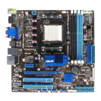
Asus M4N68T-M LE Specifications

General IconGeneral
Form FactorMicro ATX
ChipsetNVIDIA GeForce 7025 / nForce 630a
CPU SocketAM3
Maximum Memory8GB
Memory TypeDDR3
Storage Interface4 x SATA 3Gb/s
Audio ChipsetRealtek ALC662
LAN10/100/1000Mbps
Video Ports1 x VGA
CPU TypePhenom II, Athlon II, Sempron
Memory Slots2
Expansion Slots1 x PCIe x16, 1 x PCIe x1, 2 x PCI
Audio6-channel HD Audio
LAN ChipsetRealtek 8211CL
PS/22 (keyboard/mouse)
Dimensions24.4cm x 18.8cm
Power Pin24-pin ATX
USB Ports10 x USB 2.0 (4 rear, 6 internal)

Related product manuals