1-18
Chapter 1: Product introduction
• Forafullyconguredsystem,werecommendthatyouuseapowersupplyunit
(PSU)thatcomplieswithATX12VSpecication2.3(orlaterversion)andprovidesa
minimumpowerof350W.
• DONOTforgettoconnectthe4-pin/8-pinEATX12Vpowerplug.Otherwise,the
system will not boot.
• WerecommendthatyouuseaPSUwithahigherpoweroutputwhenconguringa
systemwithmorepower-consumingdevices.Thesystemmaybecomeunstableor
maynotbootupifthepowerisinadequate.
• Ifyouwanttousetwohigh-endPCIExpressx16cards,useaPSUwith1000Wpower
orabovetoensurethesystemstability.
• Ifyouareuncertainabouttheminimumpowersupplyrequirementforyoursystem,
refertotheRecommendedPowerSupplyWattageCalculatorathttp://support.asus.
com/PowerSupplyCalculator/PSCalculator.aspx?SLanguage=en-us for details.
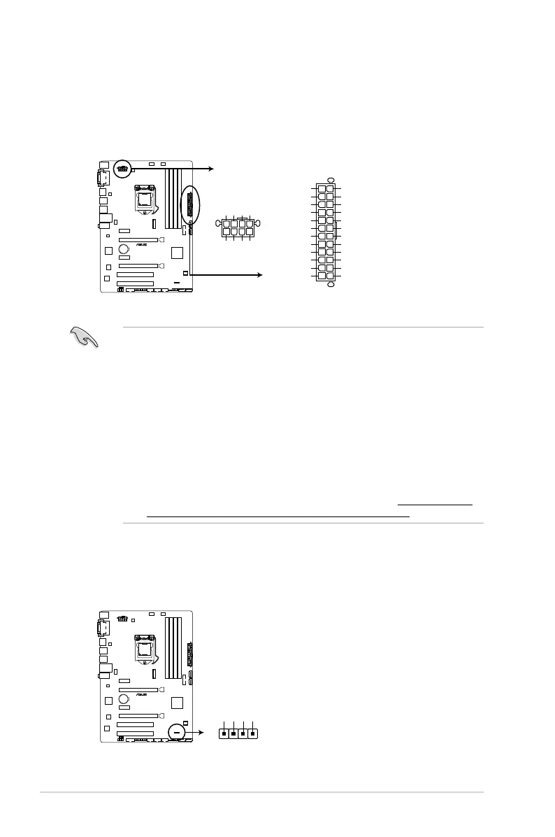
6. ATX power connectors (24-pin EATXPWR; 8-pin EATX12V)
TheseconnectorsareforATXpowersupplyplugs.Thepowersupplyplugsare
designedtottheseconnectorsinonlyoneorientation.Findtheproperorientationand
pushdownrmlyuntiltheconnectorscompletelyt.
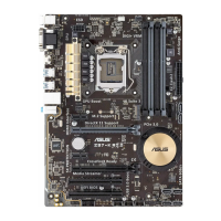
Z97-P
Z97-P ATX power connectors
EATXPWR
EATX12V
PIN 1
+12V DC
+12V DC
+12V DC
+12V DC
GND
GND
GND
GND
PIN 1
GND
+5 Volts
+5 Volts
+5 Volts
-5 Volts
GND
GND
GND
PSON#
GND
-12 Volts
+3 Volts
+3 Volts
+12 Volts
+12 Volts
+5V Standby
Power OK
GND
+5 Volts
GND
+5 Volts
GND
+3 Volts
+3 Volts
7. Speaker connector (4-pin SPEAKER)
The 4-pin connector is for the chassis-mounted system warning speaker. The speaker
allows you hear system beeps and warnings.
Z97-P
Z97-P Speaker connector
+5V
GND
GND
Speaker Out
SPEAKER
PIN 1
 Loading...