2 SETUP
2.1 LOCATIONS & FUNCTIONS
10
1 9
8
2
7
3 4 5 6
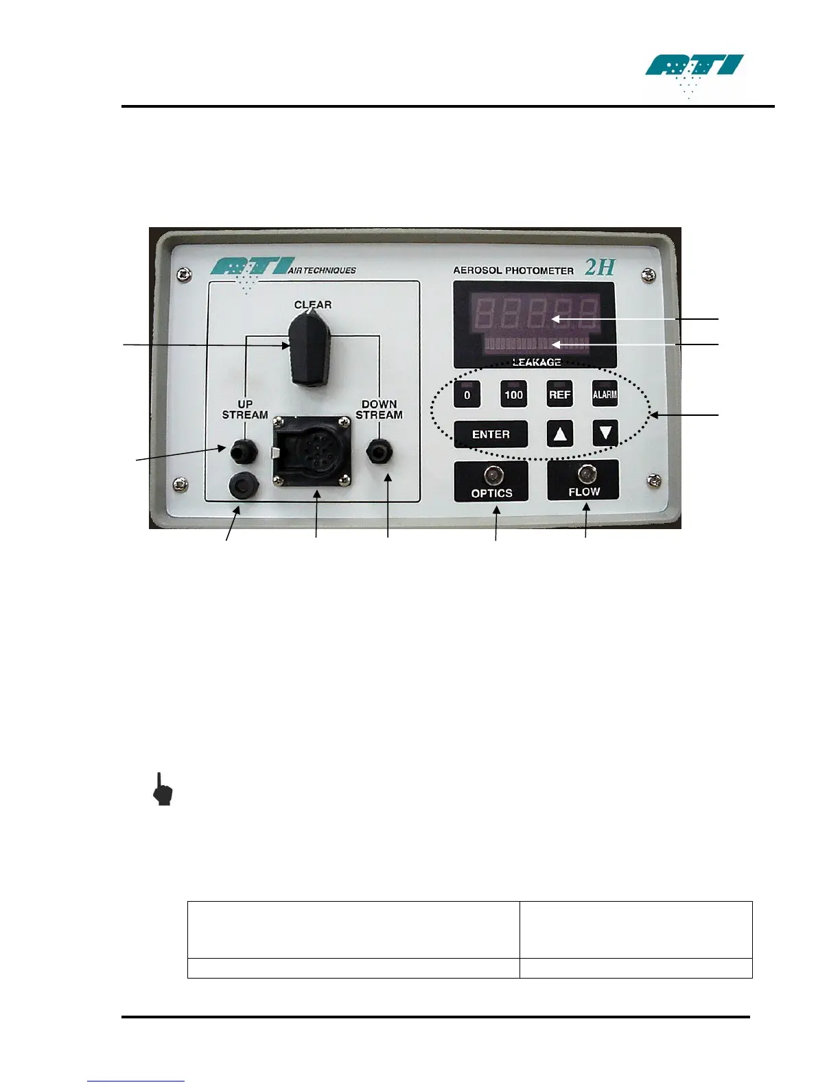
Figure 1. Front View
1. Selector Valve. Selects the sample source.
2. Upstream Sample Port. Connects to the sample tubing that is used to measure the upstream
aerosol concentration.
3. Scanning Probe Ground Jack. Electrical ground connection for scanning probe shielding.
(Required for CE compliance)
4. Scanning Probe Connector. Electrical connection for the optional Scanning Probe.
NOTE: Connect the Scanning Probe before applying power to the 2H. Failure to do so
will result in the lack of operation of Scanning Probe’s display. If this occurs, simply
turn off the power to the unit and restart the system.
5. Downstream Sample Port. Connects to the sample tubing or optional Scanning Probe that is
used to measure the downstream sample.
6. Optics indicator light. Corresponds to the cleanliness of the optics.
Green Light Less than 10,000mg* of aerosol
has moved through the
scattering chamber.
Orange Light More than 10,000mg* but less
Revision A
7

 Loading...