than 17,000mg* of aerosol has
moved through the scattering
chamber.
Red Light More than 17,000mg* of aerosol
has moved through the
scattering chamber. Servicing of
the unit is highly recommended.
* Note: These values are approximate. Actual mass may vary with different airflow rates and
aerosols.
7. Flow indicator light. Displays green when flow is within 5% of 1 CFM, yellow when flow is
from 5% to 10% of 1 CFM, and red when flow is more than 10% above or below 1 CFM.
8. Function Keys. Used for setting operating parameters and initiating program routines
9. Bar Graph Display. Displays an analog representation of the % leakage to aid in isolating
leaks.
10. Front Panel Display. Indicates % leakage readings and error messages.
2.2 FRONT PANEL CONTROLS AND INDICATORS
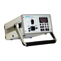
The front panel contains seven pressure-activated function keys. The <0>, <100>, <REF>, and
<ALARM> keys each contain a red LED to indicate the state of the switch or to prompt the
operator. The <Δ> and <∇> keys are used to scroll among selections as they are shown on the %
LEAKAGE display. The <ENTER> key serves as the command key for sending information to
the processor and for initiating or stopping system routines. The <Δ>, <∇>, and <ENTER> keys
contain no indicator LED.
The % LEAKAGE display is an array of high-visibility LEDs that forms a display screen. The
Front Panel Display shows alphanumeric messages. Below it is a Bar Graph Display that gives a
visual indication of internal photometer cycling or an analog representation of quantity or
percentage.
The Scanning Probe contains an unlabeled display on the pistol grip that is a half-scale duplicate
of the % LEAKAGE Indicator. The two displays are driven by the same electronics and will
always read exactly the same.
The Selector Valve, the Scanning Probe connector, and the two barbed fittings are discussed later.
2.3 SCANNING PROBE CONNECTIONS
If using the 2H with the Scanning Probe, connect the probe’s electrical connector to the 12-pin
connector on the front panel of the 2H before applying power to the photometer. Otherwise, the
display on the Scanning Probe will not function. Connect the probe’s sampling hose to the barbed
DOWNSTREAM fitting to the right of the 12-pin connector. The cable and sampling hose are
Revision A
8

 Loading...