CIRCUIT DIAGRAM
2954 2100 01 53
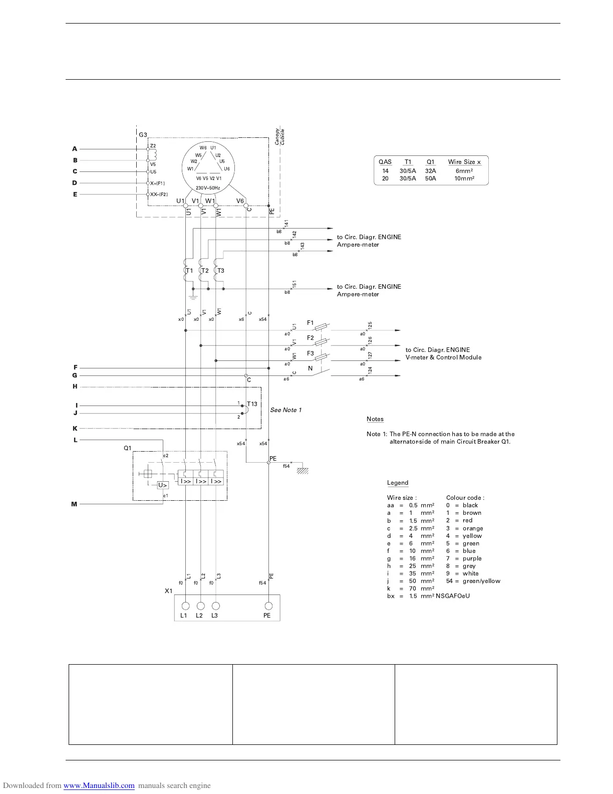
B11 Speed Sensor MPU (O) R5 Coolant Heater (O) U1 Battery Charger (O)
F1-F3 Fuses 4A R11 Speed Adjustment (O) V7 Free-wheeling Diode Y7
G3 Alternator R12 Voltage Adjustment (O) X1 Terminal Board
K7 Aux. Relay for Y7 (O) S2a (see Engine Circuit) X9 Terminal Strip
N11 Speed Controller (O) S2b Emergency Stop X11 Connector Speed Control J1
N12 Automatic Voltage Regulator S13 E.L.R. Disable-switch (O) X12 Connector Speed Control J2
N13 Earth Leakage Relay (O) T1-T2 Current Transformers (O) Y7 Air Inlet Shutdown Valve (O)
N14 IT Relay (O) T3 Current Transformer Y11 Actuator ESR (O)
Q1 Circuit Breaker T13 Torus Earth Leakage (O) (O) Optional Equipment
!
! "# $ !%%&!% ' ! ( )'* ' +
# ',-%'!-$&* !. )'&% &-/& 0-'1- 2
! &-2 3&'4-2 5
$)- 6 !%-!, 7!*/,
! &-2 3&'4-2 5
8)9-$)-
! &-2 3&'4-2 5
8)9-$)-
4%*
&- & "
''# :# 2#));
'# :# # ));
(# :# 2#));
# :# 2#));
*# :# <# ));
# :# # ));
.# :# # ));
4# :# # ));
# :# # ));
&# :# # ));
=# :# # ));
1# :# ># ));
(?# :# 2#)); @8A
!,!/- !* "
# :# (,'1
# :# (-!B%
# :# -*
# :# !-'%4
<# :# C,,!B
# :# 4-%
# :# (,/
># :# 9/-9,
# :# 4-C
# :# B&
<#:# 4-%DC,,!B
8@
<
D8
D8
8
8
&- @& ?
));
));
. . . .<
? ? ? ? ?<
?< ?<
.<
E
'
'
'
'
'
<
'
>
'
'
(
(
<
(
<
(
<
5EE 5EE 5EE
F
GHI
HI
A
B
C
D
E
F
G
H
K
L
M
I
J

 Loading...


