User guide EN TPS Control
24
© Atlas Copco Industrial Technique AB - 9836 5819 01
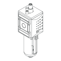
2. Press VAL to confirm the selection.
3. Press ESC to leave the menu.
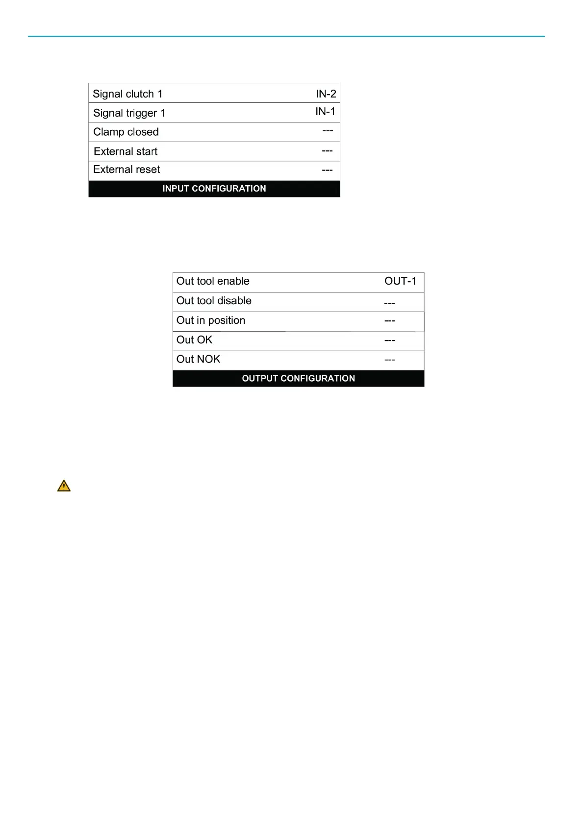
4. Go to Output Configuration and set the output signals as seen in the figure below.
5. Press VAL to confirm the selection.
6. Press ESC to leave the menu.
Installing an I/O extension board
WARNING Make sure the TPS is disconnected from power mains before opening the TPS Con-
trol unit.
Required tools:
■
Phillips screwdriver
■
Slotted screwdriver
■
Allen key
Installation procedure:
1. Remove the protective strips carefully from the front panel.
2. Using a Phillips screwdriver, unscrew the screws on the front panel.
3. Lift the front panel carefully to open the controller casing.
4. Disconnect the cables from the connectors on the main board situated inside the front panel.
5. Remove the plastic cover from I/O port 2 with a slotted screwdriver. Make sure that no parts of the
plastic cover, including the metal clips holding the plastic cover, are left inside the controller casing.
6. Connect the additional I/O board into the empty slot for I/O port 2.
7. Fasten the board with the bolts, using an Allen key from the outside.
When using the additional I/O board as an I/O extension board, make sure the board is equipped with
jumpers (in closed position).
8. Disconnect the flat band cable from the original I/O board for easier connection of the additional I/O
board.

 Loading...