User guide EN TPS Control
32
© Atlas Copco Industrial Technique AB - 9836 5819 01
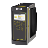
TPS I/O Power Focus I/O
Output 2 (Pin 3) Pset Select Bit 0 (Pin 15/16)
Output 3 (Pin 4) Pset Select Bit 1 (Pin 17/18)
Output 4 (Pin 10) Pset Select Bit 2 (Pin 19/20)
Input 1 (PIN 17) OK (Pin 1/2)
Input 2 (Pin 5) NOK (Pin 4/5)
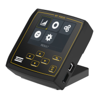
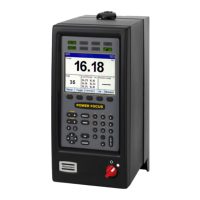
Communication between TPS and MicroTorque G4 and MT6000
This section gives an example of how to set up I/O communication between TPS and MicroTorque G4.
Recommended cable: 4222 1734 XX (01 = 1.5 m, 03 = 3m)
TPS I/O MicroTorque G4 I/O
Output 1 (Pin 2) Disable (Pin 20)
Output 2 (Pin 3) Pset Select Bit 0 (Pin 15)
Output 3 (Pin 4) Pset Select Bit 1 (Pin 16)
Output 4 (Pin 10) Pset Select Bit 2 (Pin 17)
Input 1 (PIN 17) OK (Pin 5)
Input 2 (Pin 5) NOK (Pin 6)
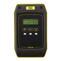
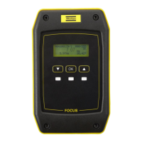
Communication between TPS and MicroTorque Focus 400
This section gives an example of how to set up I/O communication between TPS and MicroTorque Focus
400.
Recommended cable: 4222 1735 XX
TPS I/O MicroTorque Focus I/O
Output 1 (Pin 2) Tool Disable (Pin 8)
Output 2 (Pin 3) Pset Select Bit 0 (Pin 9)
Output 3 (Pin 4) Pset Select Bit 1 (Pin 10)
Input 1 (PIN 17) Tightening OK (Pin 3)
Input 2 (Pin 5) Tightening NOK (Pin 4)
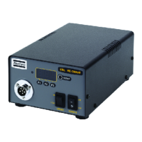
Communication between TPS and EBL RE-Drive
This section gives an example of how to set up I/O communication between TPS and EBL RE-Drive.
Recommended cable: 4222 1733 XX
TPS I/O Cable colour EBL RE-Drive I/O
Output 1 (Pin 2) Yellow SET
Output 2 (Pin 3) Brown RESET
Input 1 (PIN 17) Blue COMP
Parameters
The system parameters, as well as a number of special functions, can be accessed from the Setup menu.
To facilitate navigation, the Setup menu is divided into the following subgroups:
■
System parameter
■
Input configuration
■
Output configuration

 Loading...