User guide EN TPS Control
4
© Atlas Copco Industrial Technique AB - 9836 5819 01
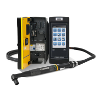
The TPS can either be used with a single tool or be connected to a torque arm that holds the tool. If the
controller is used with a torque arm, the arm is equipped with an analogue and an SSI encoder that can
detect the position of the screw being handled.
The TPS primarily monitors the sequence of screws and the tightening program, with and without position
control.
The TPS can easily be connected to different tool controllers using digital 24 VDC signals. These digital
input and output signals are used to enable and control workstations. The OK/NOK classification of the in-
dividual tightening operations is handled by the tool controllers which transmit these results through the
digital input signals to the TPS Control. The TPS has 10 digital inputs and 6 digital outputs.
In TPS, the complete sequence definition for a work piece is called a job. The TPS can store up to 50 jobs
with a total of 500 sequence element memories for positions used for these jobs. These sequence ele-
ments can be freely allocated to the 50 supported jobs. Each position within a job can be assigned to a
specific Pset, or several positions can be assigned to the same Pset. Psets are configured in the Tool-
sTalk software, which contains the complete set of parameters that control the tightening process.
TPS Control can also handle additional functions, such as input queries defined for specific positions and
external starting signals and output signals used in clamping procedures.
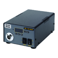
TPS Control can either be powered with an external power supply unit or through an external power signal
from the tool controller. The external power supply unit and cord are ordered separately. Note that an ex-
ternal power supply unit is required for air tools, MicroTorque and EBL RE-Drive.
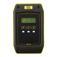
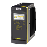
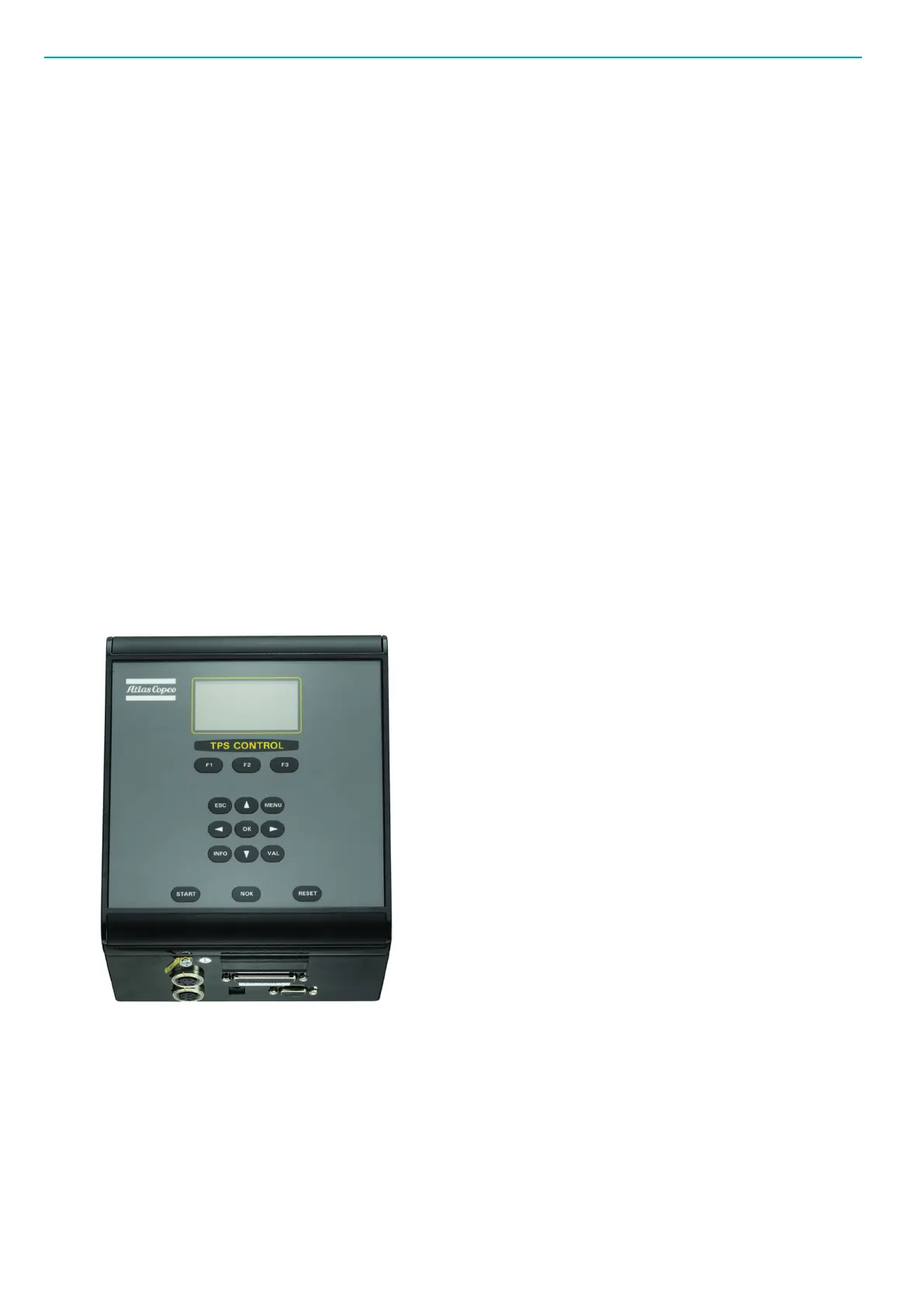
TPS controller
The main part of the TPS Control system is the TPS controller. It is contained in a metal casing with a
front panel and connection interface on the short side of the unit. The front panel can be rotated 180 de-
grees to house the connections on the top or the bottom of the unit, depending on how the controller will
be installed.
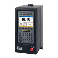
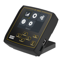
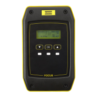
User Interface
You operate the controller using the front panel, which has a graphical display and a keyboard with special
keys and navigation keys. The display has a resolution of 128 x 64 pixels and supports different fonts and
text sizes as well as graphics. The display backlight has four colour options: red, green, blue, or white
colour.

 Loading...