Version 6.0 17 March 2010
Installation Manual 2. Installing the Device
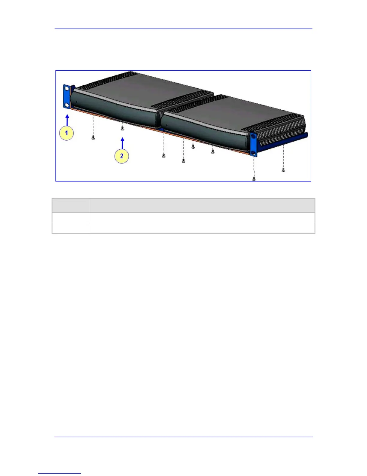
3. Attach the shelf to the rack using four standard rack screws (not supplied).
Figure 2-5: MP-11x Rack Mount
Table 2-3: MP-11x Rack Mount
Item # Functionality
Standard rack holes used to attach the shelf to the rack.
1
Eight shelf-to-device screws.
2
2.1.4 Cabling the MP-11x
This section describes the MP-11x cabling procedures:
To cable the MP-11x:
Connecting to the Ethernet network (refer to 'Connecting MP-11x to the Network'
18
on
page ).
Connecting to FXS/FXO devices (refer to 'Connecting MP-11x to FXS /FXO Devices'
18
on page ).
Cabling the FXS Lifeline (refer to 'Cabling the MP-11x/FXS Lifeline' 19 on page ).
Serial connection to a computer (refer to 'Connecting MP-11x RS-232 Port to a PC'
20
on
page ).
Connecting to the power supply (refer to 'Connecting MP-11x to Power' 21 on page ).
Once you have completed the above hardware installation steps and after powering-up the
MP-11x, the Ready and Power LEDs on the front panel light up green (after a self-testing
period of about two minutes). Any malfunction in the startup procedure changes the Fail
LED to red and the Ready LED is turned off (for details on the MP-11x LEDs, refer to
'Monitoring Front-Panel LEDs' 55 on page ). Once you have cabled the device, you can
begin configuring the device (refer to 'Configuring the Device' 35 on page ).

 Loading...