Hardware Installation Manual 20 Document #: LTRT-28030
3.3.1 CPU Module
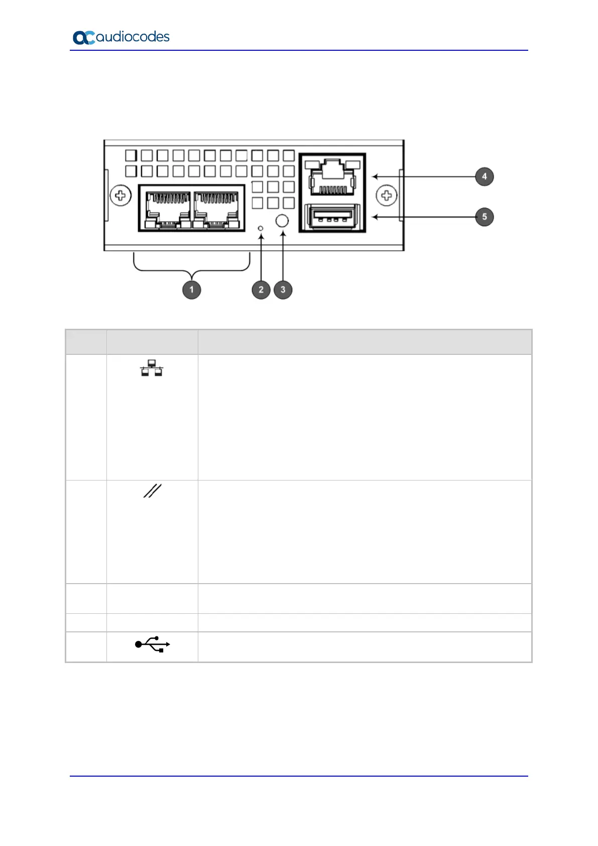
The CPU module provides the central processing unit and port interfaces, as shown in the
figure below and described in the subsequent table.
Figure 3-5: CPU Module
Table 3-8: CPU Module Description
Item # Label Description
1
Two 100/1000Base-T (Gigabit) Ethernet ports (RJ-45) for connecting to
the IP network.
The ports support the following features:
1+1 Ethernet port redundancy
Half- and full-duplex modes
Auto-negotiation
Straight or crossover cable detection
The ports provide LEDs to indicate Ethernet status. For more
information, see Section 3.3.4.1 on page 24.
2
Reset pinhole button for resetting the device and restoring factory
defaults:
To reset the device: Using a paper clip or any other similar pointed
object, press and hold down the button for at least 2 seconds but no
longer than 10 seconds.
To restore the device to factory defaults: Using a paper clip or
any other similar pointed object, press and hold down the button for
at least 10 seconds but no longer than 30 seconds
3
STAT
LED indicating the status of the CPU module. For more information, see
Section 3.3.4.2 on page 24.
4
|O|O|
RJ-45 port for RS-232 serial communication.
5
USB Type-A port which can be used, for example, for various storage
capabilities to an external USB hard drive or flash disk (disk on key).

 Loading...