Hardware Installation Manual 56 Document #: LTRT-28030
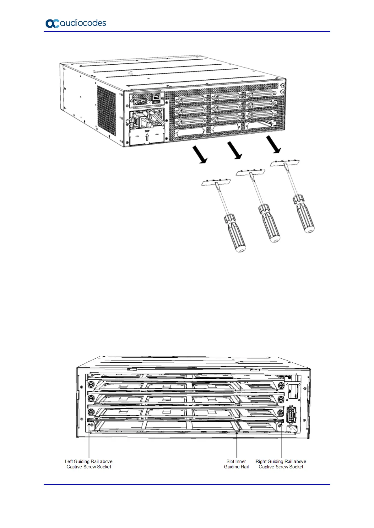
Figure 6-14: Removing Cover Plates
3. On the front panel, remove the Fan Tray cover and Fan Tray module, as described in
Section 6.2 on page 48.
4. Hold the blade on its front where the captive screws are located, making sure that you
do not touch the blades electrical components.
5. On the chassis front panel, orientate the FXS blade as shown in Figure 6-11, and then
gently slide the blade into the slot, keeping the left side of the blade aligned with the
left guiding rail located above the captive screw socket, and ensuring that the notch on
the underside of the blade is aligned to the left of the inner guiding rule, as shown in
the figure below. Slide the FXS blade into the slot until it has engaged with the chassis
backplane:
Figure 6-15: Slot's Guiding Rails for FXS Blade

 Loading...