Hardware Installation Manual 36 Document #: LTRT-28030
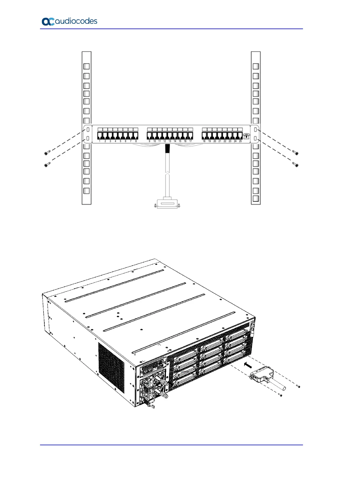
Figure 5-8: Mounting Patch Panel in Rack
2. Connect the Patch Panel's 50-pin male connector to one of the FXS blade's 50-pin
female Telco connectors located on the chassis' rear panel, and secure the connector
with the two captive screws located on either side of the connector, using a flat-head
screwdriver:
Figure 5-9: Connecting 50-Pin Telco Connector to Port on FXS Blade
3. Connect your analog equipment to the Patch Panel, by plugging the RJ-11 connectors
into the RJ-11 sockets on the Patch Panel's front panel:

 Loading...