13
4 MAINTENANCE AND CLEANING
Periodic maintenance is an “obligation” required by the law and is essential
tothesafety,efficiencyanddurationoftheboiler.Itallowsforthereductionof
consumption,pollutingemissionsandkeepingtheproductsafe and reliable
over time. Before starting maintenance operations:
close the fuel and water taps of the heating and domestic hot water sy-
stem.
To ensure product characteristics and efficiency remain intact and to comply
withprescriptionsofcurrentregulations,itisnecessarytorendertheapplian-
ce to systematic checks at regular intervals. When carrying out maintenance
work,respecttheindicationsgiveninchapter
“1 WARNINGS AND SAFETY
”.
This normally means the following tasks:
removing any oxidation from the burner
removing any encrustation from the heat exchangers
checkthestateofdeteriorationoftheelectrodeand,ifitisdeteriorated,
replace it together with the relative seal
check and general cleaning of the exhaust and intake pipes
checking the external appearance of the boiler
checkingtheignition,switch-offandoperationoftheappliance,inboth
DHW and heating mode
checkingthesealonthecouplingsandonthegas,waterandcondensate
connection pipes
checking the gas consumption at maximum and minimum output
checking the gas failure safety device.
b
During boiler maintenance, the use of protective clothing is
recommended to avoid any risk of personal injury.
b
Aftercarryingoutthemaintenancetasks,ananalysisofthecombustion
products is needed to make sure the boiler is working correctly.
b
In the event that, after any replacement of the electronic board,
exchanger,fan/mixer,gasvalve,orhavingcarriedoutmaintenance
on the detection electrode or on the burner, the analysis of the
combustion products returns values that are out of tolerance, it is
necessary to repeat the procedure described in paragraph “3.8
Combustion analysis”.
b
Do not clean the appliance or its parts with inflammable substances
(e.g.petrol,alcohol,etc.).
b
Donotcleanpanels,paintedpartsandplasticpartswithpaintthinner.
b
Panel cleaning must be carried out only with soapy water.
Cleaning the primary heat exchanger
Switch off the electrical supply by turning the system’s main switch to “Off”.
Close the gas shut-off valve.
Remove the casing as explained in paragraph “2.5 Removing the casing”.
Disconnect the connecting cable of the electrode.
Disconnect the power cables of the fan.
Take out the clip of the fixing ramp (A) from the mixer.
Loosen the nut of the gas train (B).
Rotate and take out the gas ramp from the mixer.
Remove the 4 nuts (C) that fix the combustion unit.
Take out the air/gas conveyor assembly including the fan and mixer,
being careful not to damage the insulating panel and the electrode.
Remove the siphon connecting pipe from the condensate drain fitting of
the heat exchanger and connect a temporary collecting pipe. At this point
proceed with the heat exchanger cleaning operations.
Vacuum out any dirt residue inside the heat exchanger,being careful
NOT to damage the retarder insulating panel.
Clean the coils of the heat exchanger with a soft bristled brush.
DO NOT USE METAL BRUSHES THAT COULD DAMAGE THE COM-
PONENTS.
Clean the spaces between the coils using a 0.4 mm thick blade (also
available in a kit).
Vacuum away any residue produced by the cleaning.
Rinsewithwater,beingcarefulNOTtodamagetheretarderinsulation
panel.
b
In case of stubborn deposits of combustion products on the surface
oftheexchanger,cleanbysprayingnaturalwhitevinegar,takingcare
NOT to damage the retarder insulation panel
Leave for a few minutes.
Clean the coils of the exchanger with a soft bristle brush.
DO NOT USE METALLIC BRUSHES WHICH CAN DAMAGE THE
COMPONENTS.
Rinse with water, taking care NOT to damage the retarder insulation
panel.
Make sure the retarder insulation panel is undamaged and replace it if
necessary following the relative procedure.
Oncethecleaningoperationsarefinished,carefullyreassembleallthe
components,followingtheaboveinstructionsinthereverseorder.
Toclosethefixingnutsoftheair/gasconveyorassembly,useatightening
torque of 6 Nm followingthesequenceindicatedonthediecast(1,2,3,4).
Turn the power and gas feeding to the boiler back on.
Cleaning the burner
Switch off the electrical supply by turning the system’s main switch to
“Off”.
Close the gas shut-off valve.
Remove the casing as explained in paragraph “2.5 Removing the casing”.
Disconnect the connecting cable of the electrode.
Disconnect the power cables of the fan.
Take out the clip of the fixing ramp (A) from the mixer.
Loosen the nut of the gas train (B).
Rotate and take out the gas ramp from the mixer.
Remove the 4 nuts (C) that fix the combustion unit.
Takeouttheair/gasconveyorassemblyincludingthefanandmixer,being
careful not to damage the ceramic insulation panel and the electrode. At
this point proceed with the burner cleaning operations.
Cleantheburnerwithasoftbristledbrush,beingcarefulnottodamage
the insulation panel and the electrode.
DO NOT USE METAL BRUSHES THAT COULD DAMAGE THE COM-
PONENTS.
Check that the burner insulating panel and the sealing gasket are unda-
magedandreplacethemifnecessary,followingtherelativeprocedure.
Oncethecleaningoperationsarefinished,carefullyreassembleallthe
components,followingtheaboveinstructionsinthereverseorder.
Toclosethefixingnutsoftheair/gasconveyorassembly,useatightening
torque of 6 Nm.
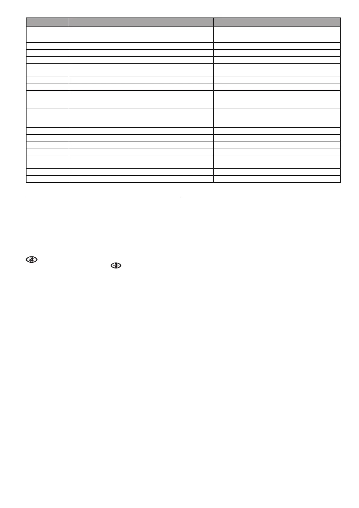
ERROR CODE ERROR MESSAGE DESCRIPTION OF TYPE OF ALARM
A10
Flame lockout
Condensate drain obstructed
Flue gas exhaust/air suction obstructed
defi nitive
A11 Extraneous fl ame transitional
A20 Limit thermostat defi nitive
A30 Fan fault defi nitive
A40 Fill the system defi nitive
A41 Fill the system transitional
A42 Pressure transducer fault defi nitive
A60 DHW probe fault transitional
A70
Flow sensor fault
Flow sensor overtemperature
Flow/return sensor diff erential
transitional
defi nitive
defi nitive
A80
Return probe fault
Return probe overtemperature
Return-fl ow sensor diff erential
transitional
defi nitive
defi nitive
A90 Flue gas probe fault transitional
A91 Clean primary heat exchanger transitional
A58 Low power supply voltage transitional
A59 High power supply voltage transitional
CFS Call Service signal
SFS Stop for Service defi nitive
FIL Low pressure - check system signal
>3.0 bar High pressure - check system signal
 Loading...