16
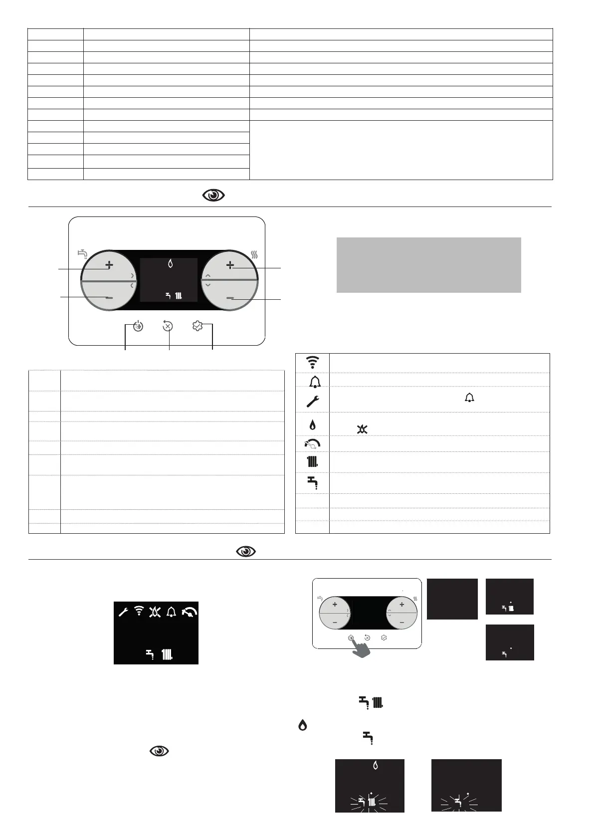
5 CONTROL PANEL
A and B
DHW setpoint adjustment
Parameter selection
C and D
Heating setpoint adjustment
Parameter setting
A+B DHW Comfort menu (on the main page and with a status other than OFF)
B
Return to previous screen/cancel choice
Press >2 sec to return to main page
1 Changeoperatingstatus(OFF,SUMMERandWINTER)
2
Reset alarm (RESET)
Interrupt venting cycle
3
Access to INFO menu
Access to parameter setting menu
Access to password entry page
ENTER function
1+3 Key lock/unlock
2+3 WhentheboilerisOFF,activatescombustionanalysis(CO)
AA
CC
BB
DD
1 2 3 1 2 3
Connection to a WIFI device
Fault or deadline timer call for service
In the event of a fault together with the icon (apart from
flame and water alarms
Indicatespresenceofflame.Intheeventofaflamefailure,the
icon is
Flasheswithtemporarywateralarms,fixedwithpermanentalarm
Present if heating mode is active; flashes with heating request
in progress
Present if DHW mode is active; flashes with DHW request in
progress
°C
Unit of measurement for temperature
rpm
Number of fan rotations
bar
Pressure value
6 USER INSTRUCTIONS
Position the system’s main switch to the “on” position.
O
pen the gas tap to allow the fuel to flow.
Whenthepowerisenabled,alltheiconsandsegmentswilllightup
for 1 sec and the firmware revision will be visualised for 3 sec:
psi
bar
rpm
°
F
°
C
888
.
The automatic venting cycle will then be launched (if it is enabled) and
willlast4min(forthedetails,refertotheparagraph“3.3Ventingcycle”).
The interface will show the status active in that moment.
b
Adjust the ambient thermostat to the required temperature (~
20°C) or, if the system is equipped with a timed thermostat or
programmer,makesureitis“active”andadjusted (~20°C).
Bring the boiler to WINTER or SUMMER mode.
6.1 Operating status
Pressingkey1,theoperatingtypeswitchescyclicallybetweenOFF-
SUMMER - WINTER and then OFF again
.
Instandby,thedisplayshowsthesystempressure,incaseofaheating
requestitshowstheowtemperature,whileincaseofadomestichot
water request the domestic hot water temperature.
°
C
5
0
4
°
C
5
0
8
---
.1
5
bar
.
temperature
DHW temperature
stand-by
The delivery temperature is shown on the display. If there is a DHW
request,theDHWtemperaturewillbeshown.
WINTER MODE
The boiler activates the heating and DHW function. The presence of the
“ ” icon indicates a heat request and burner switch-on.
SUMMER MODE
The boiler activates the traditional DHW function.
WINTER
SUMMER
°
C
5
0
8
°
C
5
0
4
Eachtimethekeysarepressed,theboilermakes
a sound signal (Buzzer); it is possible through
parameter 006 Buzzer to manage the enabling
(1) or disabling (0) of the sound.
Note:valuesinthousandsaredisplayed/100,for example
6500 rpm = 65.0
PARAMETER
NAME
DESCRIPTION
I001 Screed heater hours Number of hours of screed heater function activation
I002 Delivery probe Boiler delivery probe value
I003 Return probe Boiler return probe value
I004 DHW probe DHW probe value with boiler in instantaneous mode
I005 OT+ DHW setpoint DHW setpoint sent by OT+ remote control to the boiler
I008 Flue gas probe Flue gas probe value
I009 External probe Instantaneous external probe value
I010
External temperature for thermoregulation
Filtered external probe value used in the temperature control algorithm to calculate
the heating setpoint
I011 DHW fl ow rate DHW setpoint (only with OT+ connection)
I012 Fan rotations Number of fan rotations (rpm)
I013 Flow sensor (main zone) Value of the main zone fl ow sensor (when P4.12 = 1)
I015 Flue gas probe counter Number of operating hours of the heat exchanger in “condensing mode”
I016 Delivery setpoint (main zone) Delivery setpoint for the main zone
I017 OT+ CH setpoint Heating setpoint sent by the OT+ timed thermostat to the boiler
I018 System pressure System pressure level
I032 DHW comfort DHW comfort mode
I033 Special DHW functions Special functions active for high DHW inlet temperatures
I034 ID board Identifi cation of the electronic board
I035 FW board revision Firmware revision of the electronic board
I038 WIFI pendrive radio signal Indicates the quality of the WIFI connection
I039 ALARM LOG 1 (the oldest)
List of the last fi ve alarms recorded
I040 ALARM LOG 2
I041 ALARM LOG 3
I042 ALARM LOG 4
I043 ALARM LOG 5 (the latest)
 Loading...