37
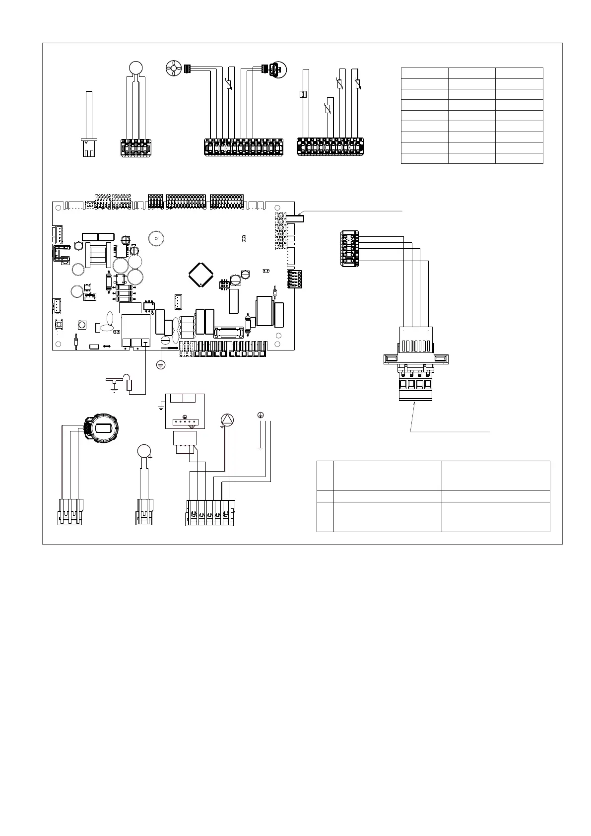
7.7 Multiwire wiring diagram • Schema electrică multilară
6
1
X1
marrone
blu
2
1
3
5
4
B: VALVOLA GAS
1 2 43
OPEOPE
rosa
blu
P
marrone
N
L
230 V
blu
blu
marrone
marrone
marrone
blu
marrone
X5
blu
V Hv
1
2
rosso (alim.) +24Vdc
blu (HS)
rosa (PWM)
grigio (-)
X13
V Lv
1
4
1
10
X19
-t°
-t°
-t°
T.L.A.
S.R.
S.M.
S.F.
rosso
rosso
bianco
bianco
grigio
grigio
blu
blu
1
X9
12
rosso
nero (alim.) +5Vdc
blu (sign.)
marrone (-)
S.S.
1
3
TP
rosso
-t°
grgio (-)
blu (sign.)
FS.
1
3
rosa (alim.) +5Vdc
1
2
bianco
X25
TBT
nero (-)
arancione (A)
giallo (B)
rosso (+24 Vdc)
-
A
B
+
C: CE4 (connettore estraibile
posizionato sotto mensola)
5
1
rosso (+24 Vdc)
giallo (B)
arancione (A)
nero (-)
X14
3
1
X4
nero (sanit.)
marrone (risc.)
blu (N)
3V
X1
X5
X4
X6
X14
X11
X19X9
X13
X21
X2
X25
ACC1
X3
F=4A T
1
10
1
12
14
5
1
14
1
5
Elettrodo
A/R
A: Utilizzare contatto privo di tensione
(Voltage free contact input)
TA
OT+
SE
AKJL01 GAR
A
Room thermostat
(voltage free contact input)
Termostat de cameră
(contactul trebuie să e liber
de tensiune)
B Gas valve Vană de gaz
C
CE4
(removable connector posi-
tioned under shelf)
CE4
(conector amovibil ModBus
sub cazan)
Multiwire wiring diagram
“L-N” POLARITY IS RECOMMENDED
AKJL01 Control board
X1-X25 Connection connectors
ACC1 Ignition transformer
E.A./R. Ignition/detection electrode
F Fuse 4A T
3V 3-way valve servomotor
V Hv Fan power supply 230 V
OPE Gas valve operator
P Pump
CE4 Connector for external connections: (- A B +) Bus 485
S.R. Temperature return sensor on primary circuit
S.M. Temperature ow sensor on primary circuit
S.F. Flue gas sensor
T.L.A. Water limit thermostat
T.P. Pressure transducer
S.S. Domestic hot water circuit temperature return sensor
F.S. Flow meter
V Lv Fan control signal
T.B.T. Low temperature limit thermostat
To connect the:
T.B.T. = low temperature thermostat it is necessary to cut in half the
white jumper marked with the word TBT present in the 2-pole
connector (X25), strip the wires and use an electric terminal
for the junction.
Blu Blue Albastru
Marrone Brown Maron
Nero Black Negru
Rosso Red Roşu
Bianco White Alb
Rosa Pink Roz
Arancione Orange Portocaliu
Grigio Grey Gri
Giallo Yellow Galben
Schema electrică multilară
ESTE RECOMANDATĂ POLARITATEA “L-N”
AKJL01 Placă de comandă
X1-X25 Conectori de conectare (X2 – X11 – X21 accesorii)
ACC1 Transformator de aprindere
E.A./R. Electrod de aprindere/de detectare acără
F Siguranţă 4A T
3V Servomotor vană cu 3 căi
V Hv Sursă alimentare ventilator 230 V
OPE Operator supapă gaz
P Pompă
CE4 Conector pentru conexiuni externe: (- A B +) Bus 485
S.R. Senzor de temperatură pe retur pe circuitul principal
S.M. Senzor de temperatură pe tur pe circuitul principal
S.F. Sondă gaze arse
T.L.A. Termostat de limitare apă
T.P. Traductor de presiune
S.S. Sondă temperatură pe retur circuit apă caldă menajeră
F.S. Debitmetru
V Lv Semnal control ventilator
T.B.T. Termostat limită temperatură scăzută
Pentru a conecta:
T.B.T. = termostat cu temperatură scăzută este necesar să tăiați în
jumătate jumperul alb marcat cu cuvântul TBT prezent în
conectorul cu 2 poli (X25), să curățați rele și să utilizați un
terminal electric pentru joncțiune.
 Loading...