6
2 INSTALLATION
2.1 Cleaning the system and characteristics of water
Inthecaseofanewinstallationorreplacementoftheboiler,itisnecessary
toclean theheatingsystem.Toensure the deviceworkswell, top upthe
additivesand/orchemicaltreatments(e.g.anti-freezeliquids,lmingagents,
etc.) and check the parameters in the table are within the values indicated.
PARAMETERS udm
HEATING CIRCUIT
WATER
FILLING
WATER
pH value - 7-8 -
Hardness °F - <15
Appearance - - clear
Fe
mg/kg
<0,5 -
Cu
mg/kg
<0,1 -
TheboilermustbeconnectedtoaheatingsystemandaDHWsystem,
both sized on the basis of its performance and power.
Beforeinstallation,washeverysystempipingcarefullyinordertoremo-
ve any residues that may impair the operation of the appliance.
Under the safety valve, install a water collecting funnel with the
corresponding discharge in the event of leaks due to the overpressure
of the heating system. The domestic hot water circuit does not need a
safetyvalve,butmakesurethatthepressureofwaterworksdoesnot
exceed6bar.Incaseofdoubts,installapressurereducer.
b
Priortoignition,makesurethattheboilerisdesignedtooperate
with the gas available; this can be checked by the wording on the
packaging and by the adhesive label indicating the gas type.
b
Itisveryimportanttohighlightthatinsomecasestheuesareun-
derpressure,sothejointsofthevariouselementsmustbeairtight.
2.2 Installation regulations
Theinstallationmustbecarriedoutbyqualiedpersonnel,incompliance
with the following reference standards: UNI 7129-7131 and CEI 64-8.
b
During boiler installation the use of protective clothing is
recommended,inordertoavoidpersonalinjury.
Always comply with local standards of the Fire Department, the Gas
Company and with possible municipal dispositions.
POSITION
This type C condensation boiler is designed for heating and domestic
hotwaterproduction.Therearetwocategories,dependingonthetype
of installation:
1. B23P-B53Pboilertype-forcedopeninstallation,withuegasdischarge
pipe and pickup of combustion air from the installation area. If the boiler
isnotinstalledoutdoors,airintakeintheinstallationareaiscompulsory;
2. C13,C13x; C33,C33x; C43,C43x; C53,C53x; C83,C83x,C93,C93x
boilertype:appliance withairtightchamber,withuegas discharge
pipe and pick-up of combustion air from outside. It does not require an
air intake point in the installation area.
The appliance can be installed indoors (g. A) or outdoors (but in a partially
protected place (g. B)whereitisnotdirectlyexposedtorain,snoworhail).
It can work within a temperature range from >0°C to +60°C.
g. B
g. A
ANTI-FREEZE SYSTEM
Theboileristtedasstandardwithanautomaticanti-freezesystemthatacti-
vates when the temperature of the water in the primary circuit falls below 5°C.
This system is always active and provides protection for the boiler up to an air
temperature in the installation area of 0°C.
To take advantage of this protection (based on burner operation), the boiler
must be able to switch itself on; any lockout condition (for ex. due to a lack of
gasorelectricalsupply,ortheinterventionofasafetydevice)thereforedeacti-
vates the protection.
Innormaloperatingconditions,theboilercanprotectitselfagainstfrost.
You are advised to add a good quality anti-freeze liquid to the primary circuit
(respectingthemanufacturer’sindications)ifthetemperaturefallsbelow0°C,
with the electricity supply disconnected and the heating system full.
Forthehotdomesticwaterpart,werecommendyoudrainthecircuit.
The boiler component materials are resistant to ethylene glycol based antifreeze
liquids.
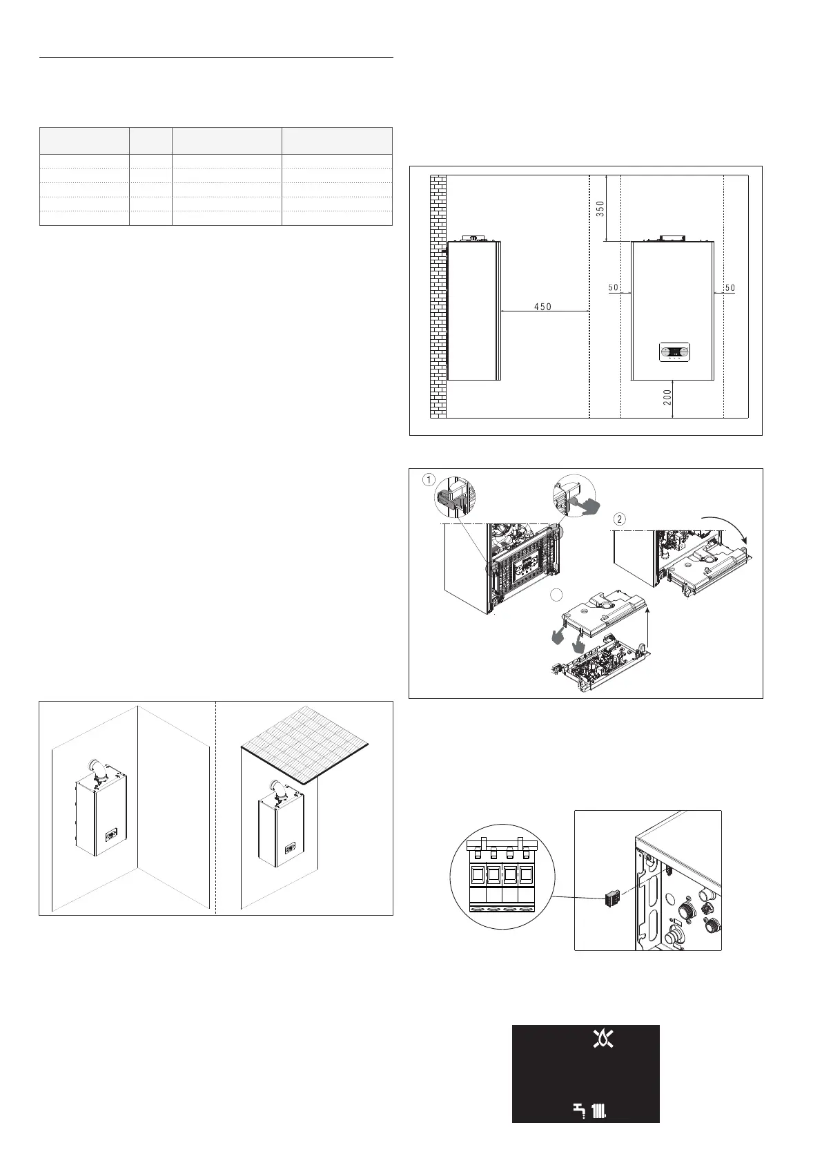
MINIMUM DISTANCES
Toensureaccesstotheboilerfornormalmaintenanceoperations,respectthe
minimum installation clearances envisaged.
Forcorrectappliancepositioning,bearinmindthat:
- it must be installed on a wall that can support its weight
- it must not be placed above a cooker or other cooking device
- itisforbiddentoleaveinammableproductsintheroomwheretheboileris
installed
- heat-sensitive walls (e.g. wooden walls) must be protected with proper in-
sulation.
measured in mm
2.3 Access to the electrical components
3
2.4 Electrical connections
Low voltage connections
CE4 connector: use4-polesconnector,suppliedasstandard,forconnections
withModBus485signal.Oncetheoperationshavebeencompleted,placethe
connector correctly in its counterpart.
b
We recommend using conductors with a section no larger than0,5mm
2
.
4-poles
ModBus
connector (CE4)
Connection on the main board: maketheTA(ambientthermostat),OT+
and SE (external sensor) connections on X11 connector - see diagram “7.5
Multiwire electrical diagram
”.
NOTE: when an OT+remotecontrolisconnectedtothesystem,ifparameter
803=1(SERVICE),
the boiler display shows the following screen
:
o
t
o
t
 Loading...