71
4.5.4 Error messages
The boiler is equipped with a self-diagnostics system in or-
der to help the maintenance personnel identify the causes
of any anomalies.
When a technical anomaly occurs, the display on the left
will either show the letter "A" or the letter "E", while the dis-
play on the right will show a numeric error code, which will
allow the maintenance personnel to identify the possible
cause.
- If the letter "A" appears on the left-hand display, this
means that the "RESET" button will have to be pressed
after the cause of the fault has been eliminated.
- If the letter "E" appears on the left-hand display, this
means that the boiler will resume functioning normal-
ly, without having to press the "RESET" button, once
the cause of the fault has been eliminated.
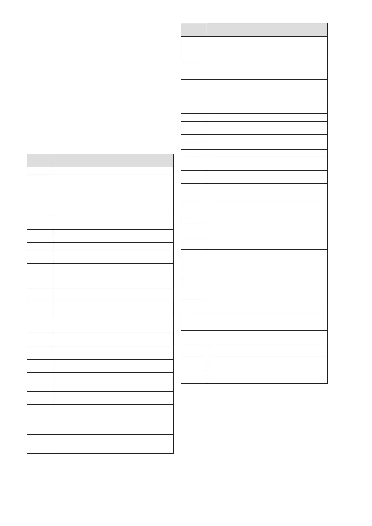
The list of the error codes and the descriptions of the rela-
tive anomalies are provided below:
Error
type
Description
A 01 No flame.
A 02
The burner turned off three times during a
request for heat.
Defective ignition transformer.
Defective ignition transformer power cord (see
fastons on the circuit board).
Flue gas pipe obstructed or partially obstruct-
ed.
A 03
The delivery temperature has exceeded the
set value.
A 04
Possible safety thermostat intervention due to
overheating.
A 05 Temporary internal fault.
A 07 (*)
Low temperature zone safety thermostat inter-
vention (if present).
A 08
The ignition relay does not work well. Press
the reset key.
If the error is permanent replace the circuit
board.
A 09
The processor RAM check is not correct.
Replace the circuit board.
A 10
The contents of the E2PROM are ruined. Re-
place the circuit board.
A 12
The values of the E2PROM do not match
those of the main software. Replace the circuit
board.
A 13
There has been a type "E" error that has not
been reset for more than 24 hours.
A 14
Internal software error. Replace the circuit
board.
A 15
Internal software error. Replace the circuit
board.
A 16
Internal software error. Press the reset key.
If the error is permanent replace the circuit
board.
A 17
Internal software error. Replace the circuit
board.
A 18
The flame was still detected after more than
10 seconds from the closure of the gas valve.
Press the reset key.
If the error is permanent replace the circuit
board.
A 19
The presence of a flame is detected more
than 10 seconds after the closure of the gas
valve.
Error
type
Description
A 20
Flame detected before the opening of the gas
valve. Press the reset key.
If the error is permanent replace the circuit
board.
A 32
Internal software error. Press the reset key.
If the error is permanent replace the circuit
board.
A 33 The fan does not spin at the proper speed.
A 34
The fan does not spin. Executes 4 cycles of 3
attempts each with A 34 resettable. The last
cycle triggers a permanent shutdown.
E 01 Delivery temperature probe open.
E 02 Return temperature probe open.
E 03
The delivery temperature, set on parameter 1,
was exceeded by 10°C for 5 seconds.
E 08 DHW tank temperature sensor open.
E 11 Delivery temperature probe short-circuit.
E 12 Return temperature probe short-circuit.
E 13
Incorrect temperature measurement. Replace
the circuit board.
E 14
Incorrect temperature measurement. Replace
the circuit board.
E 15
Incorrect temperature measurement. Check
the 16-pin J5 connector on the circuit board.
Replace the circuit board.
E 16
Incorrect temperature measurement. Replace
the circuit board.
E 18 DHW tank temperature sensor short circuited.
E 19
Not able to read the E2PROM. Replace the
circuit board.
E 20
Flame detected with gas valve closed. Internal
software error. Replace the circuit board.
E 21 Phase and neutral connections inverted.
E 23 Ground not connected. Poor grounding.
E 35
Flue temperature too high > 75°C.
Flue sensor short circuited.
E 36 Flue thermostat contact open.
E 37
Lack of water circulation. Water pressure too
low.
E 42
Communication problems. Replace the circuit
board.
E 51
Reset key error. The key was pressed more
than 5 times.
To reset the error cut off the main power.
U 10 (*)
Low-temperature system delivery temperature
probe interrupted.
U 11 (*)
Low-temperature system delivery temperature
probe short-circuit.
U 21 (*)
Delivery temperature >55°C (e.g. due to a
mixer valve fault).
U 99 (*)
Electrical power supply interruption on the
multi-temperature kit's electronic board.
(*)
Errors associated with the multi-temperature control
board (where present and enabled)
If an error not present in the table is displayed, contact the
Technical Assistance Centre.
 Loading...