CT-110-2 11
5.2.1 Mounting of pressure transmitters to HS.64 ..
HS.85 compressors
WARNING
The compressor is under pressure!
Serious injuries are possible.
Depressurize the compressor!
Wear safety goggles!
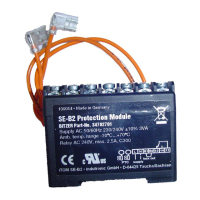
High pressure transmitter
• First, screw in the T-piece into the connection posi-
tion 1 (HP) at the compressor.
• Then, screw the high pressure transmitter to the T-
piece and connect the sensor cable.
HS.64
Fig.6: HS.64 compressor: Mounting of the high pressure transmitter
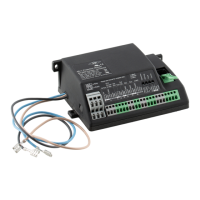
HS.74
Fig.7: HS.74 compressor: Mounting of the high pressure transmitter
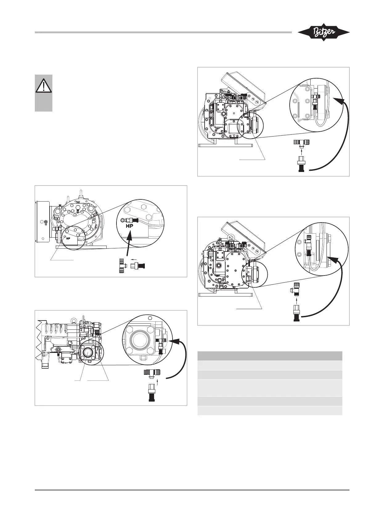
HS.8551 .. HS.8571
Fig.8: HS.8551 .. HS.8571 compressor: Mounting of the high pres-
sure transmitter
HSN8591
Fig.9: HSN8591 compressor: Mounting of the high pressure trans-
mitter
Connection positions HS. compressor
1 High pressure connection (HP)
2 Low pressure connection (LP)
3 Connection for discharge gas temperature
sensor (HP)
5 Connection/valve for oil injection
6 Oil drain (compressor housing)
Tab.3: Connection positions HS. compressor, pressure transmitter
and NTC sensor
 Loading...