CT-110-212
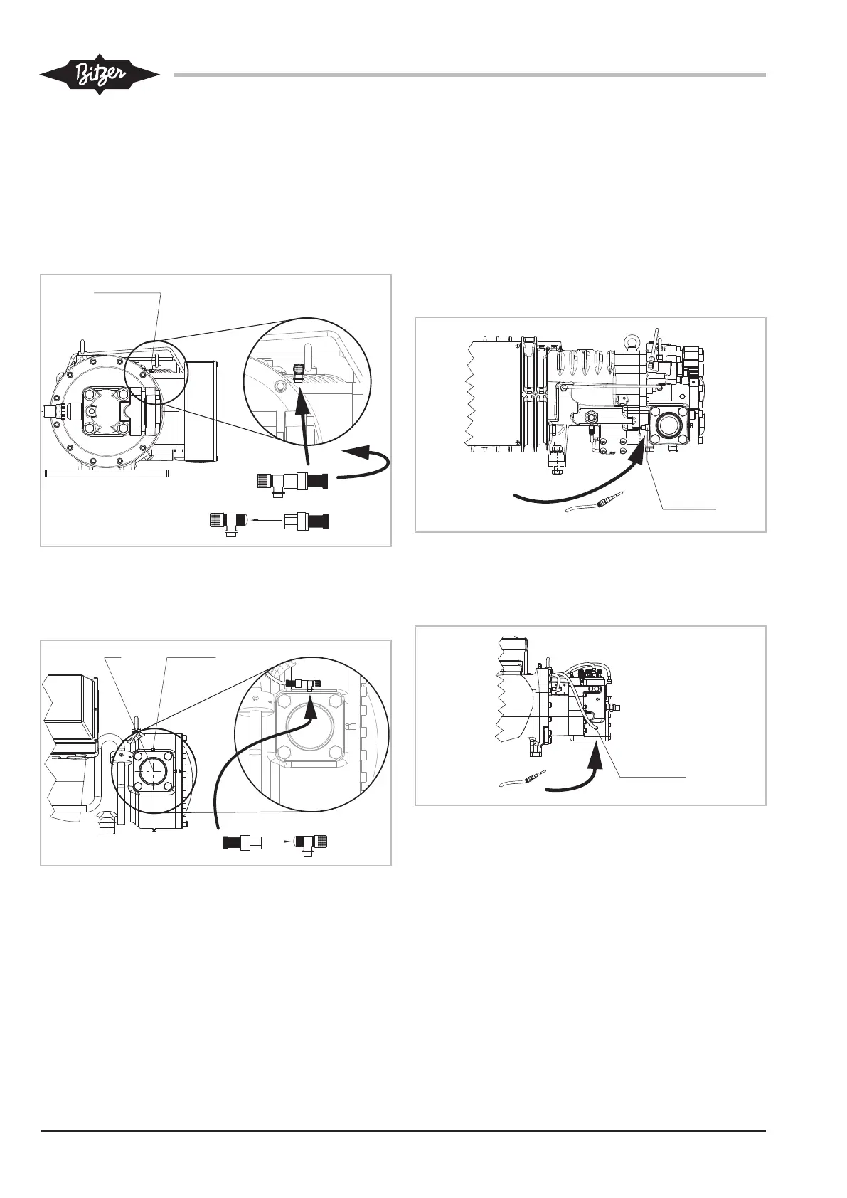
Low pressure transmitter
• First, screw in the T-piece into the connection posi-
tion 2 (LP) on the compressor.
• Then, screw the low pressure transmitter to the T-
piece and connect the sensor cable.
HS.64 .. HS.74
Fig.10: HS.64 .. HS.74 compressor: Mounting of the low pressure
transmitter
HS.8551 .. HS.8571 and HSN8591
Fig.11: HS.85 compressor: Mounting of the low pressure transmitter
Legend for connection positions, see table 3, page 11.
5.2.2 Mounting/replacement of oil temperature sensor
(PTC) with discharge gas or oil temperature
sensor (NTC) on HS. compressors
Replace the pre-installed oil temperature sensor (PTC)
at position 3 (HP) with the enclosed discharge gas or
oil temperature sensor (NTC). For this, unscrew the
PTC sensor and mount the NTC sensor at the same
position and connect it using the corresponding cable.
HS.64 .. HS.74
Fig.12: HS.64 .. HS.74 compressor: Replacing the PTC sensor with
the NTC sensor
HS.85
Fig.13: HS.85 compressor: Replacing the PTC sensor with the NTC
sensor
Legend for connection positions, see table 3, page 11.
5.3 Configuring the completion sensor kit with the
BEST SOFTWARE
Minimum settings to activate all protective and monitor-
ing functions of the SE-i1 in the BEST SOFTWARE:
• First, establish a communication via the
BEST SOFTWARE:
 Loading...