CT-110-214
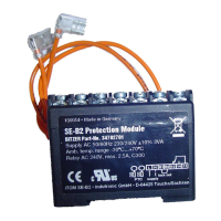
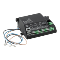
6 Electrical connection
Electrically connect SE-i1 in accordance with the
schematic wiring diagrams. Observe the safety stand-
ards EN60204, EN60364 and national safety regula-
tions.
WARNING
Risk of electric shock!
Before performing any work in the terminal box
of the compressor: Switch off the main switch
and secure it against being switched on again!
Close the terminal box of the compressor before
switching on again!
NOTICE
Potential failure of the protection device and the
motor due to improper connection and/or faulty
operation!
Connect properly according to the schematic
wiring diagrams and check the connections for
tight seat.
The cables and terminals of the PTC control cir-
cuit must not come into contact with the control
voltage or operating voltage!
6.1 Schematic wiring diagrams for CS.65 .. CS.95
compressors:
Abbr. Component
B2 Control unit (cooling demand) or command for
compressor start (release signal from the sys-
tem controller) or controller On/Off
B6 High pressure transmitter
B7 Low pressure transmitter
F1 Main fuse
F2 Compressor fuse
F3 Control circuit fuse
F4 Oil heater fuse
F5 High-pressure switch
F6 Low pressure switch
F7 Switching on delay "ECO"
F8 Oil level switch (minimum oil level), option
F9 Control thermostat "LI"
F10 Control thermostat for additional oil injection
F13 Thermal overload relay "motor" (1st part wind-
ing and star-delta)
F14 Thermal overload relay "motor" PW2
F17 Control transformer fuse
F21 Fuse of the heating element in the terminal
box
Abbr. Component
H1 Signal lamp "fault SE-i1"
H2 Signal lamp “pause time”
K1 Contactor "1st part winding" (PW) or main
contactor (star-delta)
K2 Contactor "2nd part winding" (PW) or delta
contactor (star-delta)
K3 Star contactor (star-delta)
K2T Time relay “pause time” 300 s
K3T Time relay "part winding" 0.5 sor "star-delta"
1s (CS.95: 1.5 .. 2s)
K5T Time interval relay "CR4" flashing function
on / off 10s
M1 Compressor
Q1 Main switch
R1 Oil heater
R2 Oil temperature sensor (CS.: PTC ② or NTC
➂)
R3-8 PTC sensor in motor (CS.)
R9 Heating element for terminal box
R10 Optional temperature sensor
S1 Control switch (on/off)
S2 Fault reset "SE-i1"
T1 Control transformer (example for 230V, re-
quired according to EN60204-1)
U Interference suppressor: varistor or RC ele-
ment integrated into the solenoid valve plug if
required
Y1 Solenoid valve "capacity regulator” ➀
Y2 Solenoid valve "capacity regulator” ➀
Y3 Solenoid valve "capacity regulator" ➀
Y4 Solenoid valve "capacity regulator” ➀
Y5 Solenoid valve "liquid line"
Y6 Solenoid valve "ECO"
Y7 Solenoid valve "LI"
Y8 Solenoid valve "additional oil injection"
Y9 Solenoid valve “oil cooler line”
Tab.4: Legend schematic wiring diagrams for CS.65 .. CS.95 com-
pressors
➀ Pulsing time approx. 0.5s .. max. 1s, depending on
the system characteristics.
② Included in the basic sensor kit.
➂ Included in the full sensor kit or completion sensor
kit.
 Loading...