CT-110-234
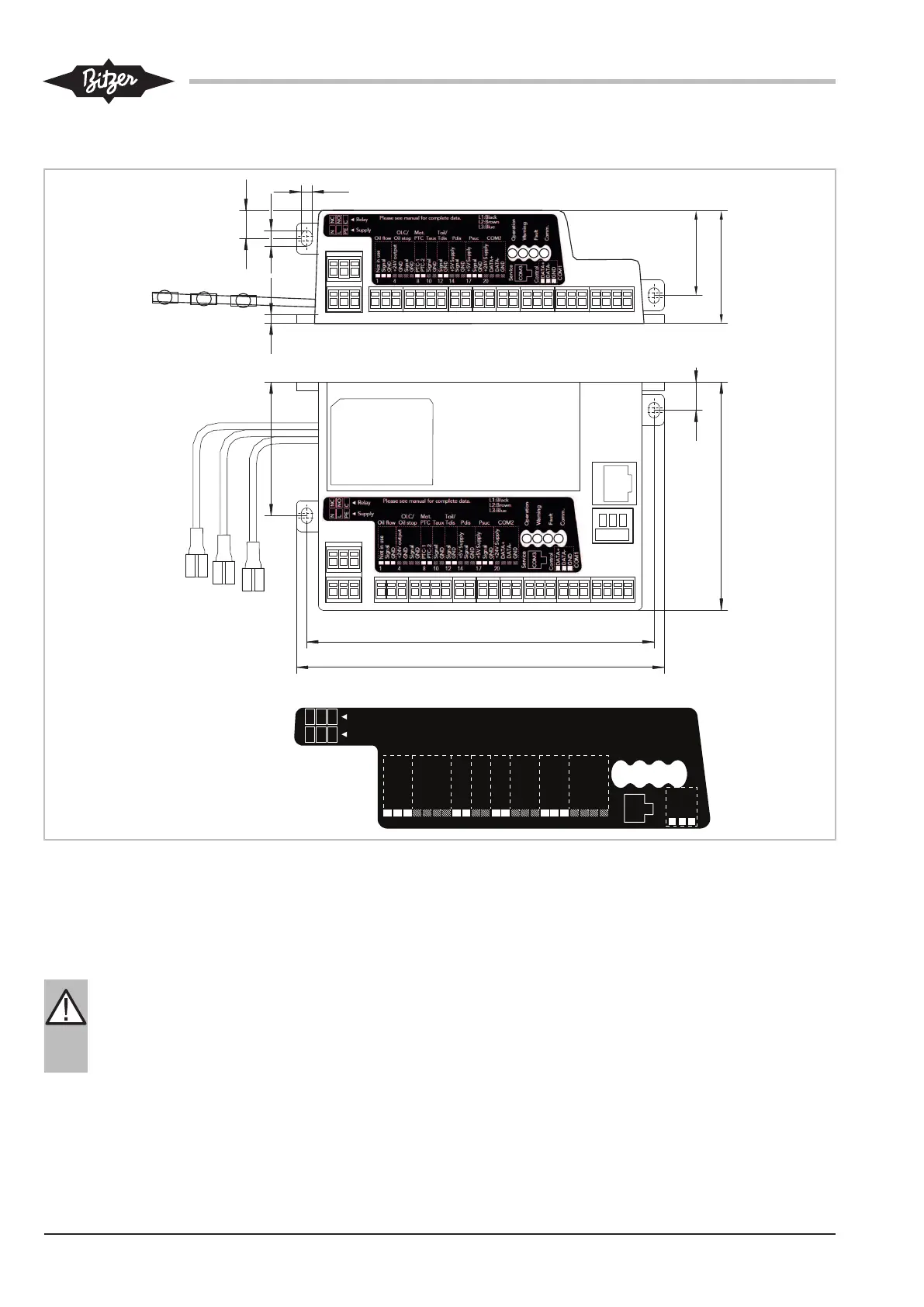
4.1 Maßzeichnung SE-i1
R
Please see manual for complete data.
L1:Black
L2:Brown
L3:Blue
Operation
Warning
Service
COM3
NC
NO
C
N
L
PE
Relay
Fault
Comm.
COM2
Not in use
Signal
GND
+24V Supply
GND
Signal
GND
PTC-1
PTC-2
Signal
GND
Signal
GND
+5V Supply
Signal
GND
+5V Supply
Signal
GND
+24V Supply
DATA+
DATA-
GND
Oil flow
Mot.
PTC
Toil/
Tdis
OLC/
Oil stop
Taux Pdis Psuc
1 4 8 10 12 14 17 20
Supply
Control
DATA+
DATA-
GND
COM1
134
11
90
53
142
34
45
3
11
4
6
Abb.2: Maßzeichung SE-i1
5 Montage und Aktivierung des Sensoren-
Komplettierungsbausatzes
WARNUNG
Verdichter steht unter Druck!
Schwere Verletzungen möglich.
Verdichter auf drucklosen Zustand bringen!
Schutzbrille tragen!
5.1 Montage der Bauteile des Sensoren-
Komplettierungsbausatzes bei CS.-Verdichtern
Die CS.-Schraubenverdichter können, mit Ausnahme
der CSHP-Verdichter, ab Werk verkabelt und ange-
schlossen, entweder mit dem SE-i1 Basis-Sensoren-
bausatz oder mit dem kompletten Sensorenbausatz be-
stellt werden. Funktionsumfang siehe Kapitel Überwa-
chungsfunktionen, Schutzfunktionen und Lieferumfang,
Seite 30.
Eine Montage aller Bauteile des Sensoren-Komplettie-
rungsbausatzes an den Verdichter ist demnach nur er-
forderlich, wenn:
 Loading...