DIVAR IP 7000 (2U) System overview | en 15
Bosch Sicherheitssysteme GmbH Installation Manual 2016.07 | V2 | DOC
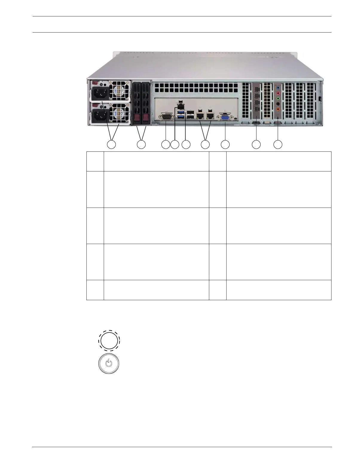
Rear view:
1 2xpower supply modules 2 2xredundant SSD drives for operating
system (RAID1 mirror)
3 1xserial port 4 1xnetwork port for BMC (Baseboard
Management Controller) connection
and IPMI (Intelligent Platform
Management Interface) monitoring
5 4USB ports 6 2xnetwork ports for data transmission
(teamed)
Note: Do not change the teaming
mode!
7 1xVGA display output (do not use!) 8 1xgraphic card (4xmini display port)
Note: Provides digital signal. An active
adapter is required to connect analog
monitors.
9 1xsound card (audio inputs and
outputs)
3.3.1 Control panel buttons
There are two push-buttons located on the front of the chassis. These are (in order from left
to right) a reset button and a power on/off button.
– Reset: The reset button is used to reboot the system.
– Power: The main power switch is used to apply or remove power from the power
supply to the system. Turning off system power with this button removes the main power
but keeps standby power supplied to the system. Therefore, you must unplug system
before servicing.
3.3.2 Control panel LEDs
The control panel located on the front of the chassis has LEDs to provide you with critical
information related to different parts of the system. This section explains what each LED
indicates when illuminated.
 Loading...