Alarm I/O connections
Alarm inputs and outputs are fitted as screw down terminal blocks on the unit. Cable cross
section is AWG 26-16 (0.13-1.5 mm2).
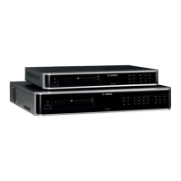
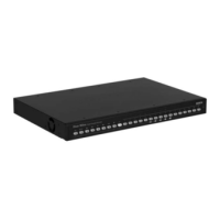
DIVAR 3000 alarms
1, 2, 3, 4, 5, 6,
7, 8, 9, 10,
11, 12, 13, 14,
15, 16
Alarm inputs: max. 16. The alarm becomes active at low voltage. Max.
input voltage 15 VDC.
NO1 C1,
NO2 C2,
NO3 C3
Three groups of normal open activation outputs (on/off button).
G Ground cable.
DIVAR 5000 alarms
1, 2, 3, 4, 5,
6, 7, 8, 9, 10,
11, 12, 13, 14,
15, 16
Alarm inputs: max. 16. The alarm becomes active at low voltage.
NO1 C1,
NO2 C2,
NO3 C3,
NO4 C4,
NO5 C5
Groups of normal open activation alarm outputs (on/off button).
CTRL +12V Control power output. Always close the device power to cancel the
alarm.
+12V External power output. Need the peripheral equipment to provide
+12 V power (below 500 mA).
G Ground cable.
Connecting the alarm input
Each (alarm) input line can be switched by a contact from an external device between a
numbered input and ground (G). Wire the inputs as either Normally Open (NO) or Normally
Closed (NC) and configure them as NO or NC in the system menu (Settings > Alarm). The
default is NO.
See the following guidelines:
– Parallel connect the COM end and GND end of the alarm detector (provide external
power to the alarm detector)
– Parallel connect the DVR ground and the alarm detector ground
– Connect the NC port of the alarm sensor to the DVR alarm input (ALARM)
– Use the same ground as the DVR if external power is used for the alarm device
– When connecting two DVRs (or one DVR and one other device), use a relay to separate
them
5.10
5.10.1
DIVAR 3000/5000 Digital Video
Recorder
Hardware setup | en 33
Bosch Security Systems Operator Manual 2013.05 | 1.0 | DIVAR 3000/5000 Digital Video
Recorder
 Loading...


