ENGLISH
D
ge
1
2
3
5
6
4
8
7
8
m = 0.125
M4 M5 M6 M8 M10
M
A1
(Nm)
8.8 2.8 5.6 9.6 23 46
R320103169/2020-08 | Linear modules MKK/MKR-xxx-NN-3 Bosch Rexroth AG 31/62
8 Mounting the MKR/MLR drive
NOTES
Risk of excessive torque and rotary speed if limits are not observed!
Avoid tension due to the weight of the motor when mounting the motor!
Damage to the product.
f Observe the specified limits.
f Install the motor in avertical position
Technical data and limits ! "Linear modules" catalog.
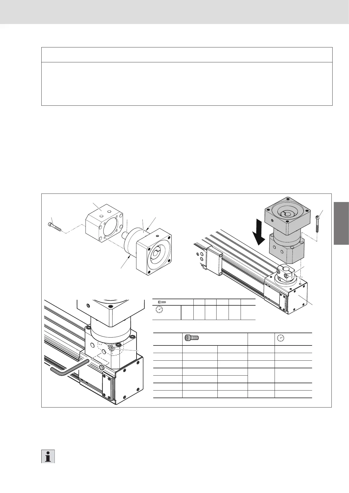
8.1 Installing the flange and gear unit
1. Attach the flange (1) to the gear (3) using 4 screws (2) M
A1
.
2. Vertically attach the gear with flange to the end enclosure(4). Centering takes place via the tubular shaft
(gearjournal and hollow shaft must be free of grease). Insert the gear journal (5) into the clamping hub (6)
and pre-assemble it with 4 screws (7) at the end enclosure (4).
3. Clamp gear journal (5) to the drive shaft with screws (8) to tightening torque M
A2
.
4. Secure gear with flange to the end enclosure (4) with 4 screws (7) to tightening torque M
A1
.
Fig�32: Mounting the MKR drive
8.2 Mounting the motor
Mount the motor onto the gear unit ! refer to the enclosed gear instructions.
When checking the function, please follow the instructions chapter 9 and 10.
MKR/MLR D
ge
(mm)
M
A2
(Nm)
-040-NN-3
M4x20-8.8 ISO4762 40
2.7
-065-NN-3
M6x20-8.8 DIN6912 60 9.5
-080-NN-3
M8x20-8.8 ISO4762 80 23.0
-110-NN-3
M10x35-8.8 ISO4762
115 46.0
-140-NN-3
M10x35-8.8 ISO4762
-145-NN-3
M8x25-10.9 ISO4762 80 34.0
-165-NN-2
M14x40-12.9 ISO4762 160 218.0
 Loading...