Table 13: Pin assignment of the power connector XD10
Plug contact Signal Function
1 24 V +24 V DC supply voltage (U
L
)
2 0 V GND (U
L
) (ground supply voltage)
10.5.3
24 V voltage supply
For the voltage supply, use a power supply unit as described in the following chapter: ⮫ Chapter 10.5.1
External power supply unit on page 23
The GND (U
L
) is not grounded in the device!
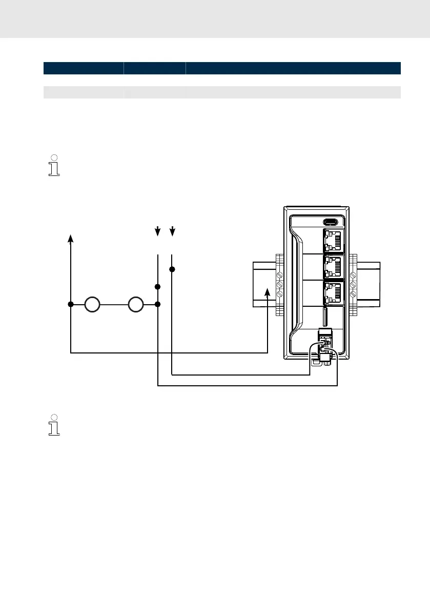
Overvoltage category I, 24 V
FE
PE
Power supply unit
Separable
connections
24 V
0 V
Fig. 12: Structure of the supply voltage
Control does not start in case of reverse input voltage
The feeding of 24 V at the XD10 connector is protected against polarity reversal. A polarity
reversal of U
L
and GND feeding does not damage the device. However, the control does not
start and the status display is not on.
Dimensioning the voltage supply
Observe the maximum currents when dimensioning the voltage supply. The operating voltage allowed
has to be applied directly to the device.
The voltage must also not be exceeded if:
• there are variations in line voltage, e.g. caused by different loads of the mains
•
there are varying load states, such as short-circuit, normal load, lamp load or no load

 Loading...