User Instructions
Tronic 1000 T | Tronic 2000 T – 6721831855 (2021/06)
162
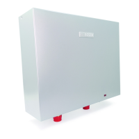
3.5.2 Horizontal installation
Fig. 3 Dimensions in mm (wall mounting, horizontal
installation, TR1000...H)
Table 3
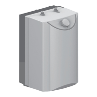
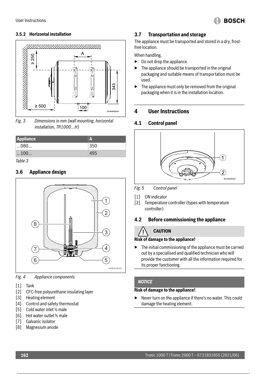
3.6 Appliance design
Fig. 4 Appliance components
[1] Tank
[2] CFC-free polyurethane insulating layer
[3] Heating element
[4] Control and safety thermostat
[5] Cold water inlet ½ male
[6] Hot water outlet ½ male
[7] Galvanic isolator
[8] Magnesium anode
3.7 Transportation and storage
The appliance must be transported and stored in a dry, frost-
free location.
When handling,
Do not drop the appliance.
The appliance should be transported in the original
packaging and suitable means of transportation must be
used.
The appliance must only be removed from the original
packaging when it is in the installation location.
4 User Instructions
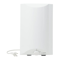
4.1 Control panel
Fig. 5 Control panel
[1] ON indicator
[2] Temperature controller (types with temperature
controller)
4.2 Before commissioning the appliance
CAUTION
Risk of damage to the appliance!
The initial commissioning of the appliance must be carried
out by a specialised and qualified technician who will
provide the customer with all the information required for
its proper functioning.
NOTICE
Risk of damage to the appliance!
Never turn on the appliance if there's no water. This could
damage the heating element.
Appliance A
...080... 350
...100... 495
163 / 242 162 / 240 163 / 242
 Loading...