Electrical connection (only for approved contractors)
167
Tronic 1000 T | Tronic 2000 T – 6721831855 (2021/06)
Make sure the cold and hot water tubes are duly identified,
in order to avoid confusion.
Fig. 12
[1] Cold water inlet (right)
[2] Hot water outlet (left)
Use suitable connection accessories for the hydraulic
connection of the appliance.
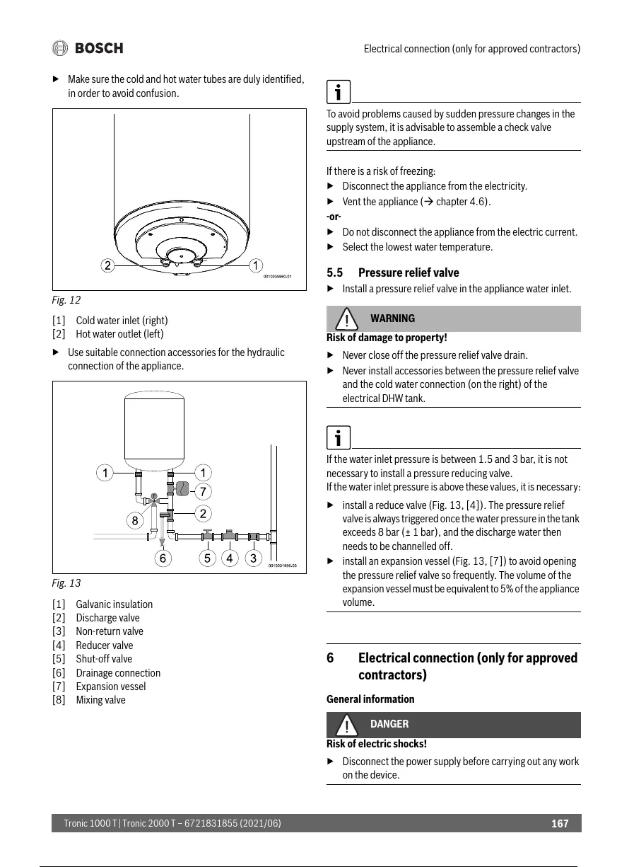
Fig. 13
[1] Galvanic insulation
[2] Discharge valve
[3] Non-return valve
[4] Reducer valve
[5] Shut-off valve
[6] Drainage connection
[7] Expansion vessel
[8] Mixing valve
To avoid problems caused by sudden pressure changes in the
supply system, it is advisable to assemble a check valve
upstream of the appliance.
If there is a risk of freezing:
Disconnect the appliance from the electricity.
Vent the appliance ( chapter 4.6).
-or-
Do not disconnect the appliance from the electric current.
Select the lowest water temperature.
5.5 Pressure relief valve
Install a pressure relief valve in the appliance water inlet.
WARNING
Risk of damage to property!
Never close off the pressure relief valve drain.
Never install accessories between the pressure relief valve
and the cold water connection (on the right) of the
electrical DHW tank.
If the water inlet pressure is between 1.5 and 3 bar, it is not
necessary to install a pressure reducing valve.
If the water inlet pressure is above these values, it is necessary:
install a reduce valve (Fig. 13, [4]). The pressure relief
valve is always triggered once the water pressure in the tank
exceeds 8 bar (± 1 bar), and the discharge water then
needs to be channelled off.
install an expansion vessel (Fig. 13, [7]) to avoid opening
the pressure relief valve so frequently. The volume of the
expansion vessel must be equivalent to 5% of the appliance
volume.
6 Electrical connection (only for approved
contractors)
General information
DANGER
Risk of electric shocks!
Disconnect the power supply before carrying out any work
on the device.
168 / 242 167 / 240 168 / 242
 Loading...