50
TEST PROCEDURES
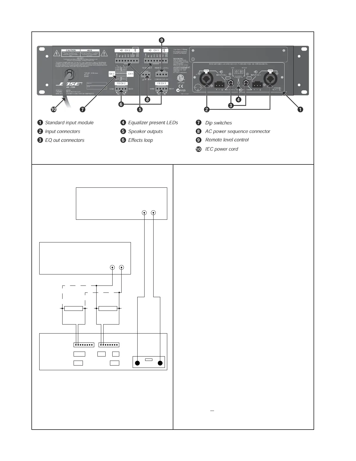
Note: Refer to figures 4 and 5 for the follow-
ing tests. Refer to the Model 2150 amplifier
owner's guide for additional operational and
hookup information.
Equipment Required:
• Audio signal generator
• Distortion analyzer
• Oscilloscope
• Digital Multimeter
• dB meter
• 2 - 4 Ohm 150 Watt load resistors
• 1 - 0.1 Ohm, 2 Watt (or greater) resistor
• 1 - 1k Ohm, 1/4 Watt resistor
• 2 - 150 Ohm terminators
1. Gain Test
1.1 On the front panel of the amplifier, set
the gain controls fully CW. On the rear panel,
set the configuration dip switches (7) OFF
(down).
1.2 Apply a 100 mVrms, 1 kHz signal to the
left and right amplifier inputs. Reference a
dB meter to the input signal.
1.3 Measure the output level at the left and
right 4 Ohm speaker outputs. It should be
30.0 dB + 0.5 dB.
4 Ohm
load resistor
4 Ohm
load resistor
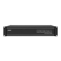
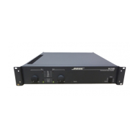
Model 2150 Amplifier rear panel
Distortion Analyzer
or dB Meter
Signal Generator
audio
inputs
speaker
outputs
outputs
inputs
COM
COM
4 Ohm
4 Ohm
8 Ohm
8 Ohm
25V
35V
50V
70V
100V
25V
35V
50V
100V
70V
Figure 5. Test Setup Diagram
Figure 4. Model 2150 amplifier rear panel
 Loading...