24
TEST PROCEDURES
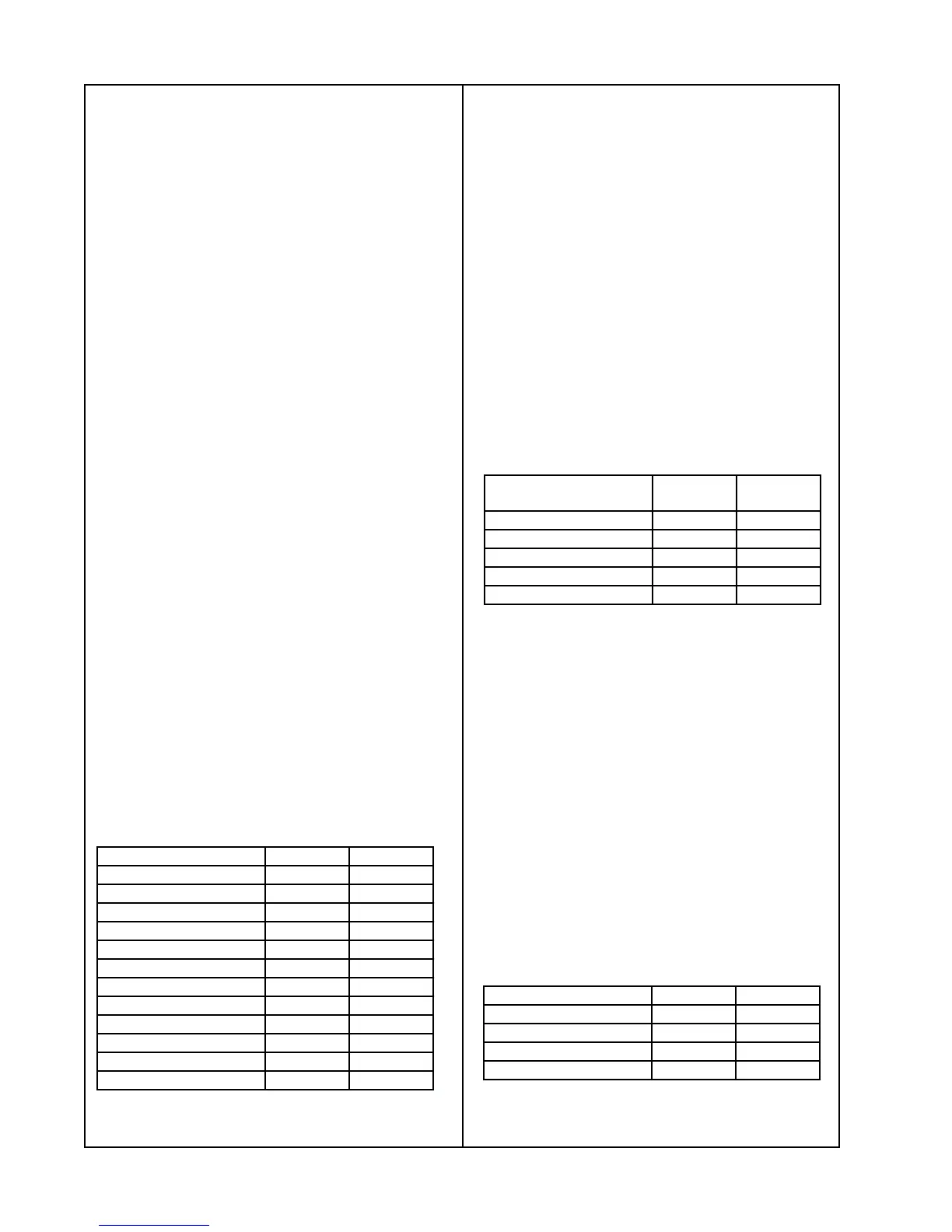
OUTPUT MIN dB MAX dB
Zone 1 L Fixed -1.5 1.0
Zone 1 L Adjustable -1.5 1.0
Zone 2 L Fixed -1.5 1.0
Zone 2 L Adjustable -1.5 1.0
Tape L -1.5 1.0
Headphone L -- -50
Zone 1 R Fixed -- -50
Zone 1 R Adjustable -- -50
Zone 2 R Fixed -- -50
Zone 2 R Adjustable -- -50
Tape R -- -50
Headphone R -- -50
1. Aux Gain and Separation Test
1.1 Apply a 2 Vrms, 1 kHz signal to the left
AUX input.
1.2 Ground the TAPE, VIDEO 1, VIDEO 2
and right AUX inputs.
1.3 Reference a dB meter to the applied
signal.
1.4 Measure the gain according to the
chart below.
Note: Repeat this test for the right channel.
General Test Setup
Use cable 184209 for fixed level tests.
Use cable 183174 for adjustable level tests.
The miniature switch number 8 on the
remote must be up to control ZONE 2.
For ZONE 1 and 2 variable tests, adjust the
volume to max.
Terminate the Headphone output into 32Ω.
Terminate all Audio outputs into 10KΩ.
Terminate the serial output jack (tip and
ring) into 10kΩ (two resistors).
See Figure 5 for adjustment locations.
3. Tape Gain and Separation Test
3.1 Apply a 2 Vrms, 1 kHz signal to the left
TAPE input.
3.2 Ground the VIDEO 1, VIDEO 2, AUX
and right TAPE inputs.
3.3 Reference a dB meter to the applied
signal.
3.4 Measure the gain according to the
chart below.
Note: Repeat this test for the right chan-
nel.
2. Video Gain And Separation Test
2.1 Apply a 2 Vrms, 1 kHz signal to the left
VIDEO 1 input.
2.2 Ground the TAPE, VIDEO 2, AUX and
right VIDEO 1 inputs.
2.3 Reference a dB meter to the applied
signal.
2.4 Measure the gain according to the
following chart.
OUTPUT MIN DB MAX
DB
Zone 1 L Fixed -1.5 1.0
Zone 1 R Fixed -- -50
Zone 2 L Fixed -1.5 1.0
Zone 2 R Fixed -- -50
Tape L -- -50
OUTPUT MIN dB MAX dB
Zone 1 L Fixed -1.5 1.0
Zone 2 L Fixed -1.5 1.0
Zone 1 R Fixed -- -50
Zone 2 R Fixed -- -50
Note: Repeat this test for the right channel
and VIDEO 2.
 Loading...