31
ALIGNMENT PROCEDURES
4.7 After the adjustment is complete,
solder the point labeled TE.
5. Alignment Completion.
5.1 Solder the point labeled ATSC.
5.2 Perform test procedure 1.
3. Focus Gain Alignment
3.1 Unplug the power pack from the CD-20
3.2 Remove the solder from the point
labeled FE and connect the CD-20 align-
ment fixture as shown in Figure 3.
3.3 Turn the CD-20 on and play track
number one of the A•Bex CD TCD-784.
3.4 Switch the CD-20 alignment fixture's
oscillator to 1.75 kHz.
3.5 Set the oscilloscope to the X-Y mode
and connect CH2 of the oscilloscope to the
"X" input and CH1 to the "Y" input of the
alignment fixture.
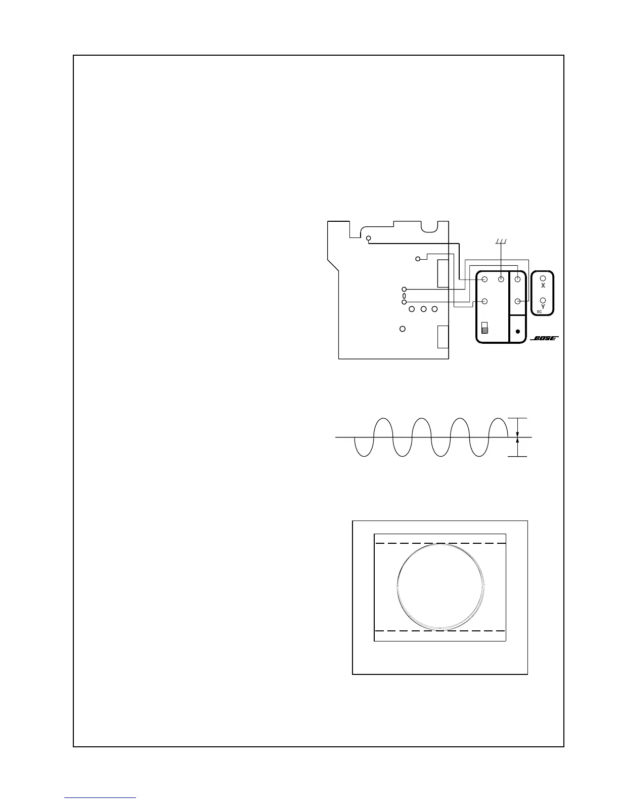
3.6 Adjust PT821 (F. GAIN) for the best
circle as viewed on the oscilloscope. See
Figure 6.
3.7 After the adjustment is complete,
solder the point labeled FE.
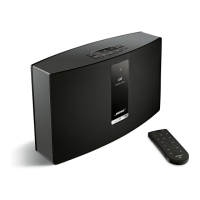
4. Tracking Gain Alignment
4.1 Unplug the power pack from the unit.
4.2 Remove the solder from the point
labeled TE and connect the alignment
fixture as shown in Figure 4.
4.3 Plug the CD-20 in and play track num-
ber 1 of the A•Bex CD TCD-784.
4.4 Switch the CD-20 alignment fixture's
oscillator to 2.15 kHz.
4.5 Set the oscilloscope to the X-Y mode.
Connect CH2 of the oscilloscope to the "X"
input and CH1 to the "Y" input of the align-
ment fixture.
4.6 Adjust PT822 (T. GAIN) for the best
circle as viewed on the oscilloscope. See
Figure 6.
CN902
CN903
TP704
Changer PCB
TP822
TP821
TE
TP701
PT822
V+
GND
1/2 V
CC
F 1.75kHz
T 2.15kHz
X
Y
SCOPE
CD20
ALIGNMENT
FIXTURE
CD-A
CD-B
POWER
Figure 5. Symmetrical Waveform
Oscilloscope
Figure 6. X-Y Mode Output
10mV/ Division
Figure 4. Tracking Gain Alignment
V1
V2
V1=V2
0V
 Loading...