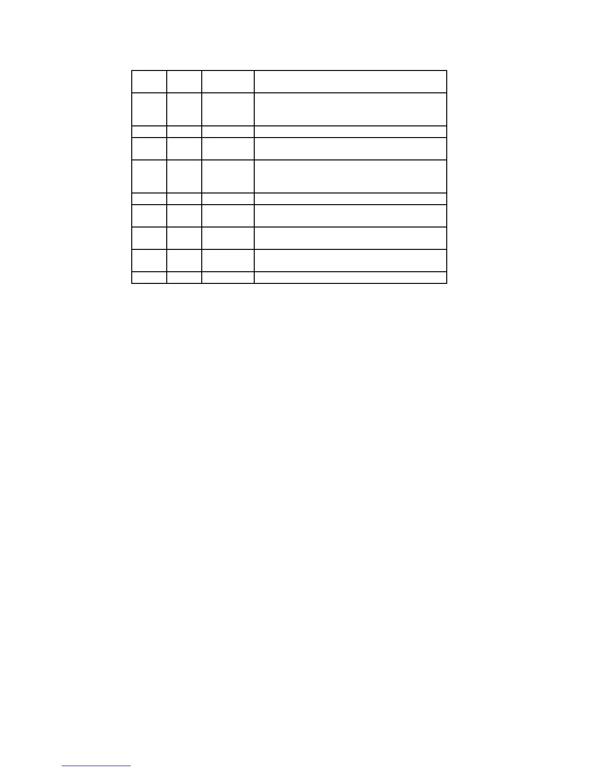
66
CD MECHANISM IC PIN CONFIGURATION TABLES
Pin
No.
I/O Terminal
Name
Description
40 - EI I-V amplifier E gain adjustment. (When
not using automatic balance
adjustment)
41 NC
42 O TEO Tracking error amplifier output. E-F
signal is output.
43 I LPFI Comparator input for balance
adjustment. (input from TEO through
LPF)
44 I TEI Tracking error input.
45 I ATSC Window comparator input for ATSC
detection.
46 I TZC Tracking zero-crossing comparator
input.
47 I TDFCT Capacitor connection pin for defect time
constant.
48 O VC (Vcc+Vee/2 DC voltage output.
IC 821 (CXA1782BQ) Servo Signal Processor RF Amplifier Table (continued)
 Loading...