29
REMOTE CONTROL ALIGNMENT
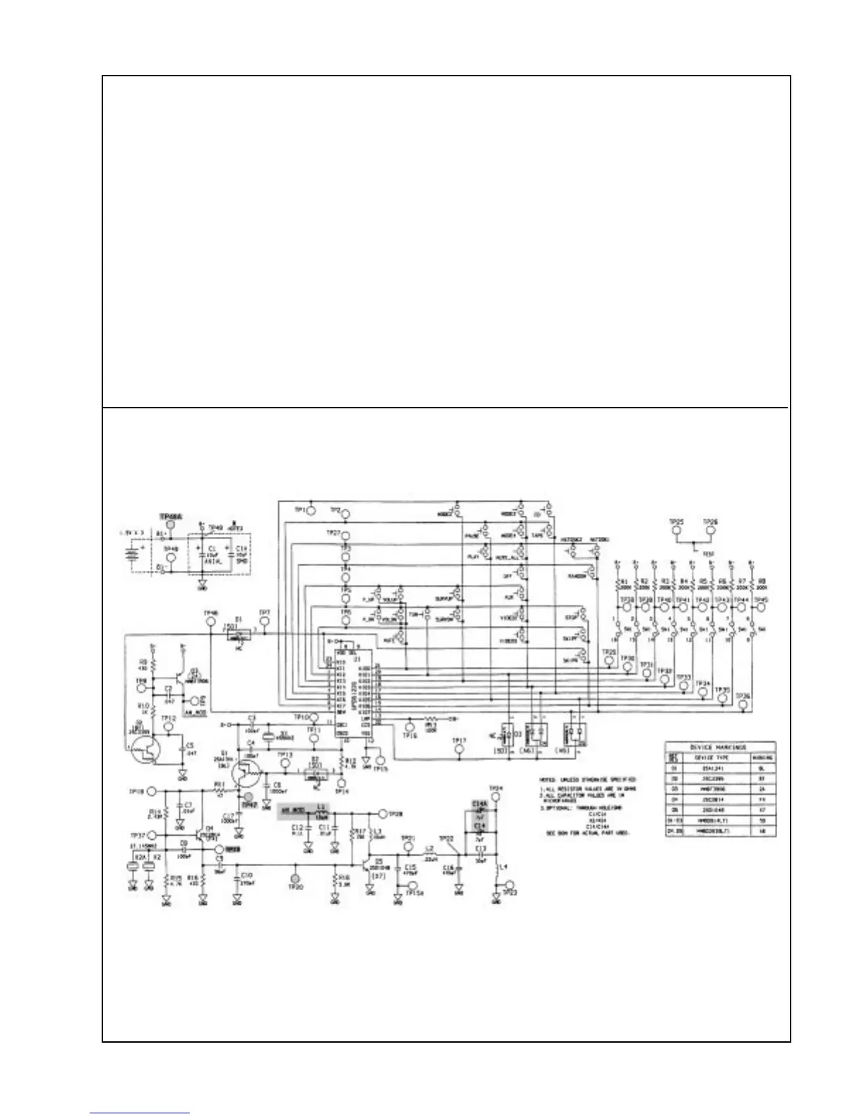
1. Remote Control Tuning
1.1 Connect TP48A (BATT +) to TP47.
1.2 Connect TP48A (BAT +) to L1 (AM MOD).
1.3 Connect an oscilloscope probe to TP22. Connect the scope ground near TP22.
Note: A x10 probe is recommended.
1.4 Rotating C14 360 degrees, you should see two points where the signal peaks.
Adjust C14 until the output at TP22 is peaked ( ≥ 6Vpp). It doesn't matter which peak you
tune to.
1.5 TP19 should be 3 Vpp. TP20 should be 1 Vpp.
Figure 6. RC-20 Tuning Locations
 Loading...