31
DISASSEMBLY PROCEDURE
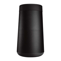
Figure 7. 1 Nut & Washer and 3 Volume Knobs
Location
CAUTION: The SMD integrated circuits used
on the Main-I/O board are extremely sensitive
to ESD damage. Be sure to use an approved
and tested ESD strap that is properly grounded
to your work bench before attempting disas-
sembly or repair of the S1 Pro+ Wireless PA
system.
1. I/O Panel Assy Removal
1.1 Use a nut driver to turn the nut anticlock-
wise to remove the nut & washer as the red
arrow indicated in Figure 7.
1.2 Remove the 3 Volume Knobs. See Figure
7.
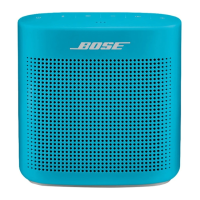
1.3 The Inlay for I/O Panel are secured with
Pressure Sensitive Adhesive - use a spudger,
lift the Inlay up and grasp and pull it o. See
Figure 8.
Note:
a. Be careful to not cause cosmetic damage to
the unit.
b. Use a blow drier to warm up the Inlay be-
fore removing the Inlay.
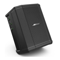
Re-assembly Note:
a. Align the edge of the replacement Inlay
along the edge shown and then press the
Inlay rmly to ensure proper adhesion.
Part Number : 867145-0010
b. Clear all the adhesive remains on the I/O
Panel before installing the new Inlay. See
Figure 9.
c. The Inlay must be properly re-applied and
completely adhered to the product with no air
leaks.
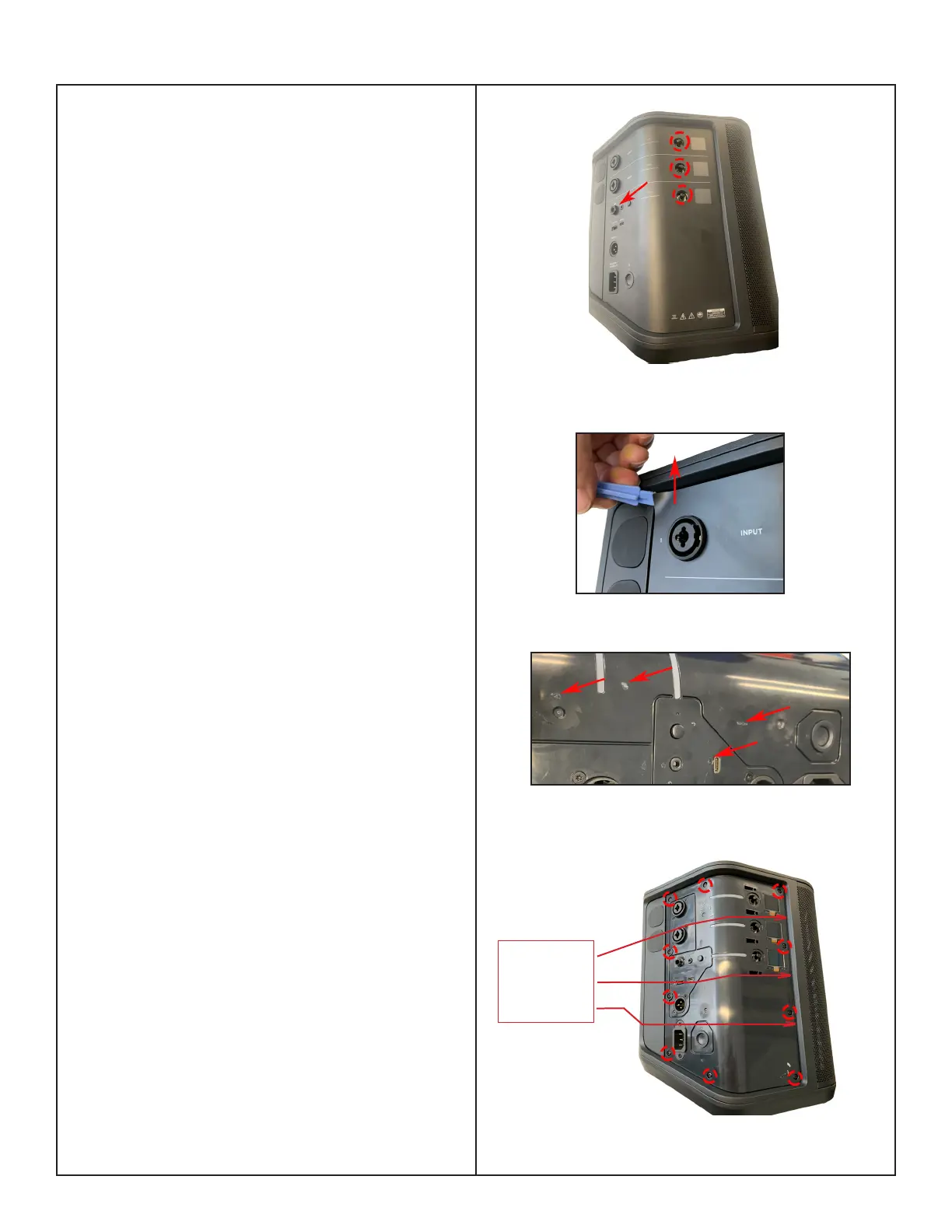
1.4 Remove the 10 screws securing the
I/O Panel as indicated in Figure 10.
Figure 8. The Inlay Removal
Figure 10. 10 screws Location
Figure 9. The Adhesive Remains on the I/O
Panel
Align the
replacement
Inlay to this
edge.
 Loading...