HTTP://WWW.FIXCLUB.COM.CN
Chapter 2
2-17
2.6 EXTERNAL AND CONTROLS SYSTEM
2.6.1 Power Supply
2.6.1.1 Power Supply
2.6.1.1.1 Low-Voltage Power Supply Circuit
0008-0490
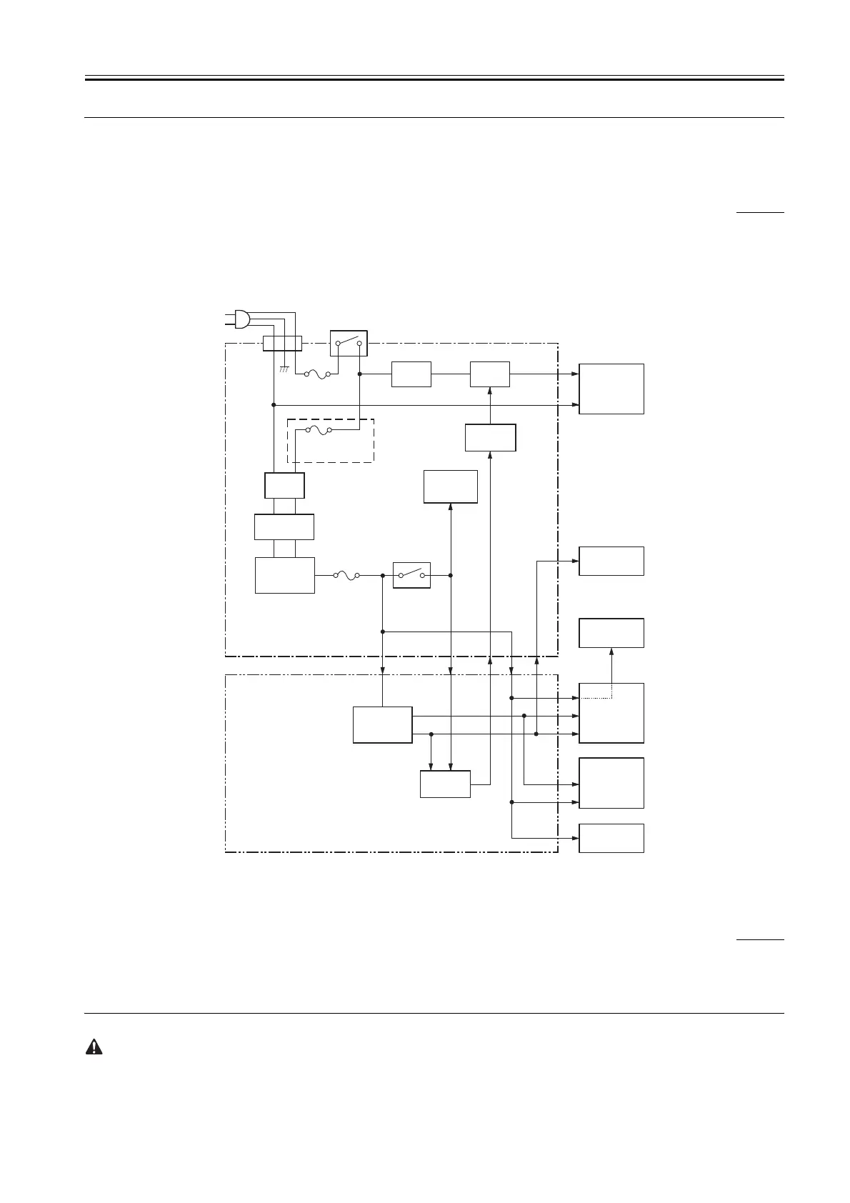
The low-voltage power supply circuit serves to convert the AC power from the power inlet into DC power for supply to various loads. The AC power is
supplied to the low-voltage power supply circuit on the power supply PCB when the power switch (SW101) is turned on. The AC power is then converted
by the printer unit into +24 V, which will then be converted into +5 V and +3.3 V in the engine controller.
The +24 V power is used to drive the main motor, scanner motor, and solenoids, while the +5 V power is used to drive the sensors and the ICs on the video
controller PCB.
The +24 V power turns to +24 V when it moves through the door switch (SW301) to reach the high-voltage power supply circuit. The +24 VU also serves
as the door open detection signal (DOSNS), enabling the CPU find out whether the door is open or not.
F-2-19
2.6.1.2 Protective Functions
2.6.1.2.1 Protective Mechanisms
0008-0493
The protective mechanisms include an overcurrent protective circuit that uses a fuse. If short circuit or the like occurs because of some fault and, as a result,
an overcurrent flows, the fuses will melt to cut off the power to the power supply circuit.
The power supply circuit is equipped with 2 fuses (Note; FU101, FU102); in the event an overcurrent flows into the AC line, either of these fuses will melt
to cut out the current. The power supply circuit also uses another fuse (FU501) to cut out the output voltage in response to an overcurrent in the DC line.
If the overcurrent protective circuit has gone on and DC voltage stops from the power supply circuit, turn off the power switch (SW101), correct the fault
in the load, replace the fuse, and turn the power switch back on.
The fuse FU102 is used only in the 110/127 V model.
Pick-up solenoid
Sensors
Main motor
Engine control PCB
Inlet
(INL101)
Power supply circui
t
ACN
ACH
Noise
filter
Relay
(RL101)
Noise
filter
DOSNS
+24V
+24V
DC/DC
converter
+24VU
CPU
(IC902)
+5V
+3.3V
Fixing heater
Fixing heater
safety circuit
Ringing choke
converter
Power switch
(SW101)
Fuse
(FU101)
Fuse
(FU102)
110-127V only
Rectification
circuit
Door switch
(SW301)
High-voltage
power supply
circuit
Video
controller
Laser/scanner
unit
Fuse
(FU501)
 Loading...