8400-0181-OM Rev C 185 and 185B Installation & Technical
10
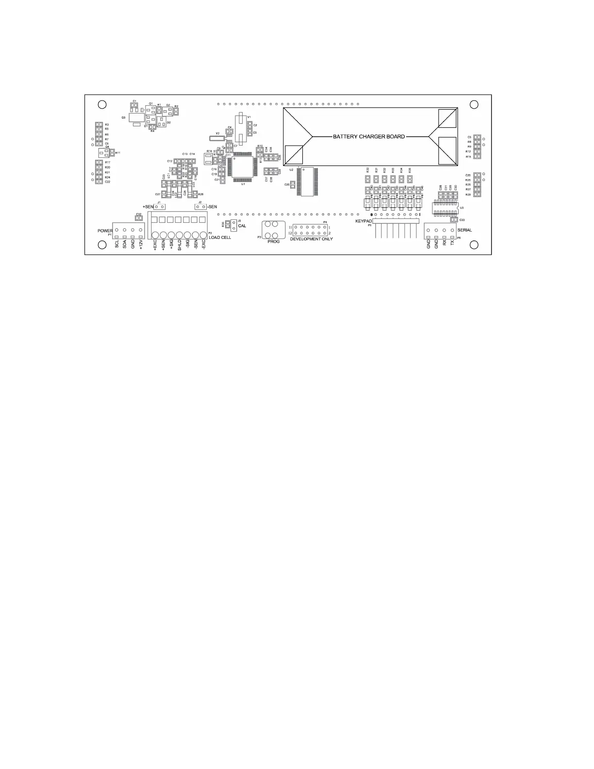
Main PCB and Jumpers
NOTE: Loosen the four captive screws securing the rear housing to the front housing, and
remove the rear housing to access the jumpers.
Figure No. 9
J3 - CALIBRATION JUMPER
Jumper J3 must be installed to operate the indicator. To begin the setup and calibration
procedure, J3 must be removed and re-installed with the indicator powered on.
J1 and J2 - SENSE JUMPERS
If sense leads are NOT used, you must install plug-in jumpers at J1 and J2 (adjacent to the P2
connector). These jumpers attach the sense leads to the excitation leads. If sense leads ARE
used, these plug-in jumpers should be positioned on one plug-in pin only or removed and
stored for later use.
Re-Installing the Rear Panel
After all terminations have been made:
1. Remove the excess cable from the indicator enclosure and securely tighten each of the
cable gland connectors.
Do not over-tighten these connectors but make certain they are snug.
DO NOT USE TOOLS! Finger-tighten only!
2. Make certain no cables or wires are exposed between the main housing and rear
panel, and then place the rear panel onto the main housing.
3. Secure the rear panel to the main housing with the four (4) Phillips screws removed
earlier, torqueing them to 20 inch-pounds (2.26 newton-metre).
J1 J2
J3
CAL

 Loading...