8400-0181-OM Rev C 185 and 185B Installation & Technical
5
INSTALLATION
Unpacking
Carefully remove the indicator from the shipping carton and inspect it for any evidence of
damage that may have taken place during shipment. Keep the carton and packing material for
return shipment if it should become necessary. The purchaser is responsible for filing all claims
for any damages or loss incurred during transit.
Should your indicator come already installed on a scale, the following
installation information does not apply to you.
Mounting
The Model 185 and 185B indicators are housed in an ABS IP66 wall or desk-mount enclosure.
The gimbal may be mounted on a desktop or other smooth, flat, horizontal surface or may be
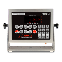
mounted on a wall. Refer to Figure No. 1 for a layout of wall-mounting bolts.
Figure No. 1
If wall mounted, make certain the mounting surface is strong enough to support the indicator.
The mounting location should be where the display is easily viewed while being close enough
to provide the operator easy access to the keypad. Carefully lay out the mounting hole
locations, then drill and install the anchor bolts. Attach the gimbal to the wall and securely
tighten the retaining bolts.
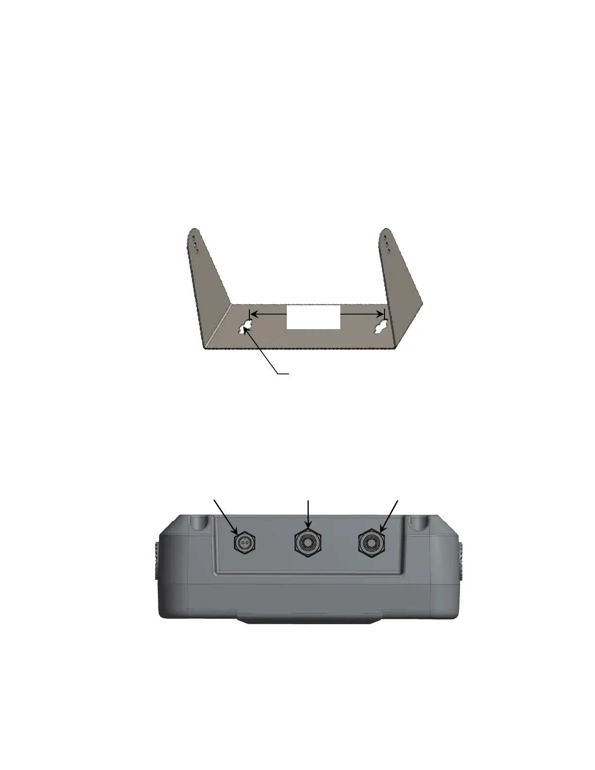
Figure No. 2
AC Power Adapter
To power the Model 185 or 185B using the 12 VDC wall plug-in AC power adapter, connect
the plug from the adapter into the power jack on the bottom panel of the indicator and then
plug the power adapter into the proper electrical outlet. Refer to Figure No. 2. On models
requiring 230 VAC, it is the customer’s responsibility to obtain the correct power adapter plug.
Load Cell
Connector
Serial Port
Connector
AC Power
Adapter
Clearance for #10
(5 mm) size screw
6.00"
(15.24 cm)

 Loading...