10
ENG
easy/easy compact/easy split +030220791 - rel. 3.2 - 13.07.2010
2. ASSEMBLY AND INSTALLATION
2.1 Assembly
Warnings:
Avoid installing the boards in environments with the following
characteristics:
• relative humidity greater than 90% or where there is condensation;
• strong vibrations or knocks;
• exposure to continuous water sprays;
• exposure to aggressive and polluting atmospheres(e.g.: sulphur and
ammonia fumes, saline mist, smoke) so as to avoid corrosion and/or
oxidation;
• strong magnetic and/or radio frequency interference (there avoid
installing the units near transmitting antennae);
• near transmitting antennae and to the elements in general;
• large and rapid uctuations in the ambient temperature;
• environments where explosives or mixes of ammable gases are
present;
• exposure to dust (formation of corrosive patina with possible oxidation
and reduction of insulation.
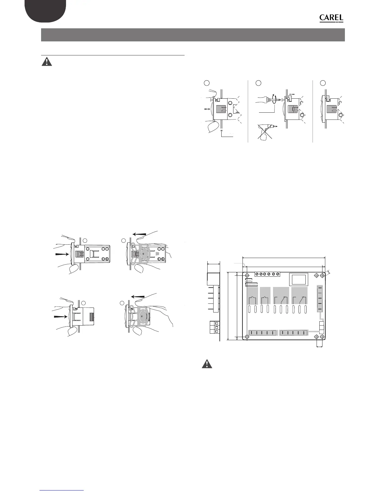
To install easy, easy compact and easy split: make an opening in the panel
based on the drilling template, 71x29 mm.
Panel installation using 2 rear brackets (Figs. 2.a and
2.b)
• insert the instrument in the opening (phase 1);
• secure the instrument by sliding the brackets in the guides on the
instrument until compressing them against the panel (phase 2);
easy
1
2
PUSH
Fig. 2.a
easy compact, easy split
1
2
PUSH
Fig. 2.b
Removing from the panel with brackets
• release the instrument by pressing both brackets where marked “push”
and sliding it back on the guides.
Panel installation from the front using screws (Fig. 2.c)
• the thickness of the fastening panel must not exceed 3 mm;
• remove the front frame and make sure that the two catches are in place
(these must not protrude from the outline of the drilling template). If
necessary, unscrew the two screws. Do not unscrew excessively, the
screws must not be detached from the front panel (phase 1);
• insert the instrument in the opening in the panel and hold it in position
by the centre of the front panel (phase 1);
• using the screwdriver, tighten the bottom screw 90°, the catch must
come out of its slot and click onto the panel, then tighten until the front
panel is secure. Do not over-tighten, when the front panel is secured
blocks simply make another ½ turn to compress the gasket; If the catch
does not click onto the panel, unscrew the screw, applying pressure at
the same time with the screwdriver so that the catch moves back. Do
not unscrew too much, the head of the screw must not be raised from
the surface of the front panel (phase 2);
• repeat the same operation for the top screw (phase 2);
• apply the front frame (phase 3).
max 2,5
1
(
*
)
2
3
Fig. 2.c
(*) do not over-tighten the screws.
Dismantling using the screws from the front
• unclip the front frame;
• unscrew the bottom screw, at the moment the front panel detaches
from the panel keep pressure on the screw and unscrew a further 90°
to make the catch go back into its slot;
• repeat for the top screw;
• remove the instrument from panel, keeping it horizontal
easy split: power board dimensions and assembly
Assembly is performed using plastic spacers or plastic turrets. The power
board is supplied upon tted in a standard case for panel mounting,
dimensions 190x140x70.
36
N
L
N
RL1
RL4
RL3
RL2
L
98
117
5
5
88
8.5
5
103.5
Ø
4
7
Fig. 2.d
Warnings:
• the connection cables must guarantee insulation at least up to 90 °C;
• spade terminals with max. operating temperature at least 100°C
• if the board is installed in an electrical panel with metal cabinet, allow
at least 10 mm distance between the cabinet and any point on the
board (rear, edges and assembly holes);
• the probe and digital input connections must be less than 10 m long,
adopt suitable measures to separate the cables for compliance with
immunity standards;
• suitably fasten the output connection cables to avoid contact with
extra low voltage components.
3 mm

 Loading...