19
ENG
easy/easy compact/easy split +030220791 - rel. 3.2 - 13.07.2010
Duty setting and defrost
If the control probe error occurs when the controller is in defrost mode,
the function is not stopped but rather is completed as required; in
addition, the defrost can still be performed when called. During the
defrost, the duty setting timer is not stopped but rather keeps counting
the ON and OFF times.
Duty setting and continuous cycle
If the continuous cycle is operating, the controller instantly exits this status
and activates duty setting (also for safety reasons, given that during the
continuous cycle the low temperature alarm is disabled). To re-activate
continuous cycle operation, the ambient probe fault must be resolved.
If the probe error is no longer present, the unit returns to normal operation.
The compressor again takes on the logic of the control, respecting the
times c1, c2, c3.
4.5 Continuous cycle
The continuous cycle is used to maintain refrigeration continuously
active, regardless of the temperature inside the unit. The function is used
to rapidly lower the product temperature, even below the set point, for
example after lling the cabinets. In this phase, the temperature may fall
below the set point. To activate or deactivate the continuous cycle from
the keypad, see paragraph 3.5, the display shows “cc” and the
icon
ashes (2 ashes, pause).
cc: continuous cycle duration
This represents the time in hours that the compressor operates
continuously for so as to lower the temperature, even below the set
point. If cc=0 the continuous cycle is not activated. The controller exits
the continuous cycle procedure after the time set for parameter “cc” has
expired, or when reaching the minimum temperature (see the minimum
temperature alarm, parameter AL).
c6: temperature alarm bypass after continuous cycle
This is the time in hours during which all the temperature alarms
are deactivated after a continuous cycle. If the temperature of the
refrigerated unit, after the continuous cycle, lowers due to inertia below
the minimum temperature threshold (set point-AL), the activation of
the low temperature alarm is delayed for the time c6. In any case, the
continuous cycle is deactivated at the temperature (set point-AL).
4.6 Compressor protection
The easy, easy compact and easy split controllers are tted with an
automatic compressor protection system to avoid continual starts or
stops of the unit. The protection is based on the times in minutes set for
parameters c0; c1; c2; c3:
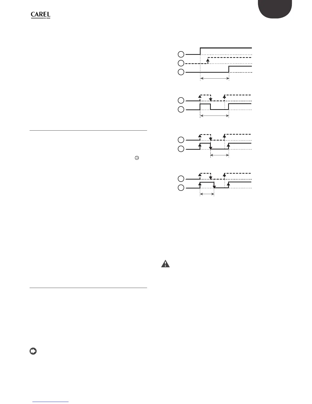
c0 compressor and fan start delay on power-up
When the controller is powered-up, this delays the start of the compressor
and the evaporator fan (see Fig. 4.c).
c1 minimum time between consecutive compressor starts
Delay between two consecutive starts of the compressor (see Fig. 4.d).
Note:
• if the maximum number of starts/hour allowed is 10, simply set c1=6
to ensure this limit is observed.
• as well as c1, also remember that parameter “dd” (dripping time) stops
the compressor and the evaporator fan after a defrost..
c2/c3 minimum compressor o /on time
These determine the minimum o time (c2) and on time (c3) for the
compressor. The compressor will not be controlled until times c2 and c3
have elapsed (see Figs. 4.e and 4.f).
OFF
OFF
ON
OFF
ON
ON
C0
1
2
3
Fig. 4.c
OFF
OFF
ON
ON
C1
3
2
Fig. 4.d
OFF
OFF
ON
ON
C2
3
2
Fig. 4.e
OFF
OFF
ON
ON
C3
3
2
Fig. 4.f
Key to Figs 4.c…4.f
1 instrument power-up;
2 compressor call;
3 compressor
c11: second compressor delay (easy split only)
This parameter determines the delay in the activation of the second
compressor compared to the main compressor. The parameter has no e ect
on the deactivation of the compressor.
Important: select the auxiliary output as the second compressor
output in parallel (H1 = 5), second compressor with two step control,
without rotation (H1 = 6) or second compressor with two step control, with
rotation (H1=7).
 Loading...